
Circulating fluidized bed boiler applicable to garbage incineration

A circulating fluidized bed and waste incineration technology, which is applied in incinerators, fluidized bed combustion equipment, and molten fuels, etc., can solve the problem of low combustion temperature, unstable combustion and low calorific value of waste in fluidized bed incinerators. and other problems, to achieve the effect of solving high temperature corrosion and coking of flue gas, improving combustion efficiency and stability, and reducing NOx generation

Inactive Publication Date: 2018-11-06
HUANENG CLEAN ENERGY RES INST
View PDF2 Cites 12 Cited by
  • Summary
  • Abstract
  • Description
  • Claims
  • Application Information

AI Technical Summary

Problems solved by technology

[0005] (1) Fluidized bed incinerators have low combustion temperature, unstable combustion, and high CO content in flue gas due to low calorific value, large compositional differences, and unstable feeding.
[0006] (2) The content of alkali metals and alkaline earth metals in waste raw materials is relatively high, and there are low-temperature eutectics and compounds with low melting points in fly ash particles, which are likely to cause blockage of air distribution devices and coking of high-temperature heat exchange surfaces
[0007] (3) Garbage fuel contains more Cl elements, and the HCl formed in the flue gas is likely to cause corrosion of the high-temperature heat exchange surface
However, the system improves the combustion effect of garbage fuel through the optimization of the overall structure, and the controllability of the combustion process is low.

Method used


Image

  • Circulating fluidized bed boiler applicable to garbage incineration

Examples


example 1

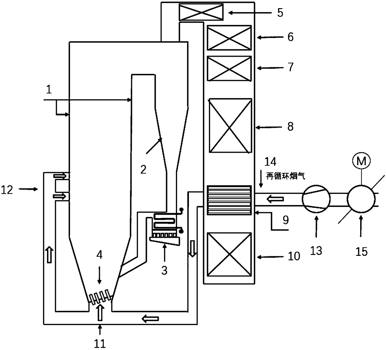
[0028] Example 1 such as figure 1 As shown, a circulating fluidized bed boiler suitable for waste incineration, including 1. adiabatic furnace, 2. high-efficiency cyclone separator, 3-external bed heat exchanger (high temperature superheater), 4-inclined air distribution plate, 5 -evaporation tube bundle, 6-water cooling tube bundle, 7-low temperature superheater, 8-coal economizer, 9-recirculation flue gas heat exchanger, 10-air preheater, 11-primary air pipe, 12-secondary air pipe. 13-recirculation flue gas booster fan, 14-recirculation flue gas pipe, 15-valve. Garbage fuel is burned in the furnace. Since the heating surface of the furnace is covered by castables to form an adiabatic furnace 1, the furnace can stably reach a combustion temperature above 850°C. Garbage is burned in the adiabatic furnace 1 to produce a large amount of high-temperature flue gas and fly ash. The high-temperature flue gas carries unburned carbon particles and recycled materials in the upper part...


PUM


Abstract

The invention discloses a circulating fluidized bed boiler applicable to garbage incineration. The circulating fluidized bed boiler applicable to garbage incineration comprises a hearth, an air distribution device, a separator, a material return valve, an external bed heat exchanger, a tail flue, a water-cooling pipe bundle, an evaporation pipe bundle, a low-temperature superheater, a coal economizer, a recirculating smoke heat exchanger, an air pre-heater and the like. According to the circulating fluidized bed boiler applicable to garbage incineration, an in-boiler water-cooling wall is completely poured-covered with a refractory material, so that a high combustion temperature of the circulating fluidized bed boiler is ensured. Meanwhile, recirculating smoke is heated by virtue of hot smoke in the tail flue, so that charge heat is increased, and the combustion stability of garbage incineration in the circulating fluidized bed boiler is further improved. The heated recirculating smokeis mixed with primary air and secondary air, so that a primary air amount used for fluidization is reduced while an air temperature is increased, the effect of enhanced graded combustion is further achieved, and the original generation of NOx is reduced. The problem of insufficient heating surface in the heat-insulation hearth is solved through arranging a high-temperature superheater in an external bed; and meanwhile, the problems of high-temperature corrosion of smoke, and coking in a biomass and garbage incineration process, are greatly solved.

Description

technical field [0001] The invention relates to the technical field of garbage incineration and circulating fluidized bed boilers, in particular to a circulating fluidized bed boiler suitable for garbage incineration. Background technique [0002] Municipal solid waste is solid waste generated in people's daily life. With the development of the economy, the output of municipal solid waste is increasing year by year. A large amount of garbage has become a long-standing source of pollution in cities. How to dispose of waste economically and effectively is an urgent problem we are facing. Efficient incineration technology is beneficial to alleviate environmental pollution caused by municipal waste. Compared with landfill and composting technology, incineration technology has a large processing capacity, can reduce the amount of landfill, solidify harmful components, and can fully recover heat energy. It is currently the most promising waste treatment technology. [0003] At...

Claims


Application Information

Patent Timeline
Patent Type & Authority Applications(China)
IPC IPC(8): F23G5/30F23G5/44F23C10/10F23C9/00
CPCF23G5/30F23C9/006F23C10/10F23G5/44
Inventor 时正海袁野高洪培赵鹏勃孙献斌肖平
Owner HUANENG CLEAN ENERGY RES INST
Learn More