
LCD technique

A technology, glass substrate technology, applied in the field of LCD technology, can solve the problems of increasing cost, high labor intensity, waste of labor cost, etc., and achieve the effect of reducing corrosion and toxicity, reducing labor intensity and improving work efficiency

Inactive Publication Date: 2018-11-06
株洲晶彩电子科技有限公司
View PDF4 Cites 4 Cited by
  • Summary
  • Abstract
  • Description
  • Claims
  • Application Information

AI Technical Summary

Problems solved by technology

[0004] (1) The material used in the powder spraying process is mainly plastic balls, which are mixed with isopropanol and water in a certain proportion. In the actual operation process, PI is usually coated first, and then powder can be sprayed after curing, friction, and silk screen printing, which will cause spraying. The powder is not uniform, and it is often charged with static electricity, resulting in poor results
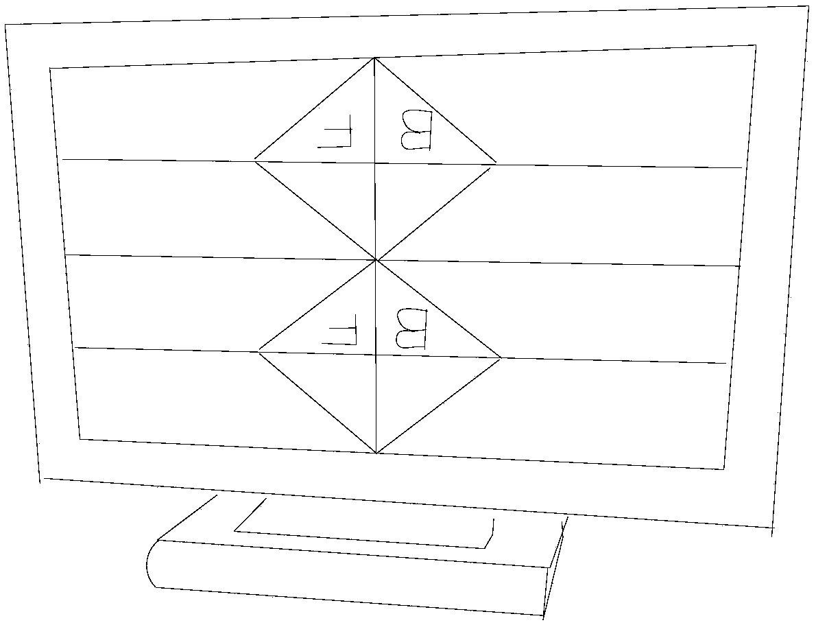
[0005] (2) Since the appearance of the LCD is basically the same, some distinctions need to be made for different product specifications. In the prior art, in order to distinguish different batches of products, the outer surface of the glass is usually marked, which wastes labor costs and is less efficient.
[0006] (3) The etchant used in the etching process is usually aqua regia composed of hydrochloric acid and nitric acid. Although the etching effect is good, the corrosion and toxicity are too strong, which is harmful to the workshop or technicians, and the processing cost is high.
[0007] (4) During the cutting process, it is necessary to cut from the cutting surface of the glass, and the order cannot be reversed. At present, manual observation is usually the main method, which is labor-intensive and easy to make mistakes.
[0008] (5) Optical properties At present, in the production process of LCD display screens, the LCD glass must be cleaned first before the glue can be applied before the LCD is loaded, and then the subsequent LCD process is carried out. The cleaning of the LCD glass before loading generally uses strong alkali Cooperating with ultrasonic cleaning machine, this method is mainly aimed at LCD glass substrates of normal quality. However, there are some B-standard or expired LCD glass substrates (stored for more than half a year for a long time), which are not cleaned thoroughly by this method and cannot be glued, resulting in The rework rate is very high. The specific reason is that when the LCD glass substrates are stored, there will be a layer of paper between the LCD glass substrates. Long-term storage will cause a lot of oil, particles, and cerium oxide residues. Therefore, this type of product is used If not, it will result in a high rework rate, time-consuming and labor-intensive, a serious waste of efficiency, or it will have to be returned at a discount, which will invisibly increase the cost of the enterprise

Method used


Image

  • LCD technique
  • LCD technique

Examples


Embodiment 1

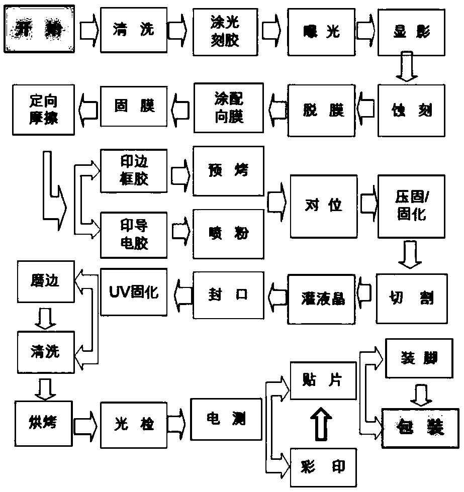
[0036] The present embodiment provides a kind of LCD technique, comprises the following steps:

[0037] S1. Pretreatment: After raw material inspection, the first cleaning, photoresist coating, exposure, development, film hardening, etching, stripping and second cleaning are carried out in order to obtain the ITO glass substrate;

[0038] S2. Applying an orientation layer and curing PI: finish coating an orientation layer and spraying powder before curing, and then curing to obtain a cured ITO glass substrate;

[0039] S3. Post-processing: The cured ITO glass substrate is rubbed with PI, silk screen, hot-pressed, cut, granulated, liquid crystal filled and sealed in sequence, and the initial production of the LCD display is completed after cleaning;

[0040] S4. Finished product processing: The preliminarily produced LCD display screen is inspected, edged, external silk screen, patched, and pinned, and finally packed into the warehouse.

[0041] Wherein, the photoresist coatin...

Embodiment 2

[0052] This embodiment is basically the same as Embodiment 1, except that in step S2, an alignment layer is applied first, then powder spraying is performed, and then curing is performed to obtain a cured ITO glass substrate.

[0053] In this embodiment, the process sequence of powder spraying is changed from after curing to before curing, which can prevent static electricity.

Embodiment 3

[0055] This embodiment is basically the same as Embodiment 1, the difference is that the raw material of the ITO glass substrate described in step S1 is hard glass, and the diamond cutter wheel of a multi-knife machine is used for cutting in step S3, and the cutting is performed with a pressure of 3 to 4 kg .

[0056] In this embodiment, hard glass is used instead of ordinary glass, and the ITO glass substrate has higher hardness and is more heat-resistant.


PUM


Abstract

The invention relates to the technical field of LCD production, and particularly discloses an LCD technique. The technique comprises the steps of S1, preprocessing: cleaning for the first time, photoresist spreading, exposure, developing, hardbaking, etching, demolding and cleaning for the second time are sequentially conducted after raw material inspection is conducted to obtain an ITO glass substrate; S2, orientation layer spreading and PI curing: orientation layer spreading and powder spraying are completed before curing is conducted, and curing is conducted to obtained the cured ITO glasssubstrate; S3, post processing: PI rubbing, silk screening, heat pressing, cutting, granulating, liquid crystal filling and sealing are sequentially conducted on the cured ITO glass substrate, and theinitial production of an LCD display screen is completed after cleaning is conducted; S4, finished product processing: detecting, outer screen printing and patching are conducted on the initially produced LCD display screen, and the LCD display screen is finally packaged and put into a warehouse.

Description

technical field [0001] The present invention relates to the technical field of LCD production, and more specifically, relates to an LCD process. Background technique [0002] liquid crystals—substances that combine the properties of liquids and crystals over a certain temperature range. Liquid crystals have an electro-optic effect. The electro-optic effect of liquid crystals refers to an electrical light modulation phenomenon in which the molecular arrangement of liquid crystals changes under an external electric field, which causes the optical properties of the liquid crystal cells to change accordingly. Because liquid crystals have dielectric anisotropy and conductance anisotropy, an external electric field can change the alignment of liquid crystal molecules and perform light modulation. At the same time, due to birefringence, it can show special properties such as optical rotation, light interference and light scattering. [0003] With the advancement of science and te...

Claims


Application Information

Patent Timeline
Patent Type & Authority Applications(China)
IPC IPC(8): G02F1/13G02F1/1333
CPCG02F1/1303G02F1/1333
Inventor 尹泽轩
Owner 株洲晶彩电子科技有限公司
Learn More