
An electrolytic capacitor manufacturing device and method integrating laser cutting and welding

An electrolytic capacitor and laser cutting technology, applied in laser welding equipment, welding equipment, manufacturing tools, etc., can solve the problems of low production efficiency, need for turnover, preparation and clamping, loss of sealing of capacitors, etc.

Active Publication Date: 2020-11-13
HUBEI SANJIANG AEROSPACE HONGFENG CONTROL
View PDF7 Cites 0 Cited by
  • Summary
  • Abstract
  • Description
  • Claims
  • Application Information

AI Technical Summary

Problems solved by technology

[0004] At present, the packaging and sealing of military electrolytic capacitor shells commonly used in the industry adopts laser welding technology, but grinding wheel grinding or other cutting processes with mechanical stress are generally used in the later cutting process of positive electrode materials. Micro cracks, in the later use process, this kind of micro cracks will continue to expand with environmental changes, and eventually cause the capacitor to lose its sealing and fail
At the same time, the product needs turnover, preparation and clamping from sealing welding to positive electrode material cutting, resulting in long production cycle and low production efficiency

Method used


Image

  • An electrolytic capacitor manufacturing device and method integrating laser cutting and welding

Examples


Embodiment Construction

[0029] In order to make the object, technical solution and advantages of the present invention clearer, the present invention will be further described in detail below in conjunction with the accompanying drawings and embodiments. It should be understood that the specific embodiments described here are only used to explain the present invention, not to limit the present invention. In addition, the technical features involved in the various embodiments of the present invention described below can be combined with each other as long as they do not constitute a conflict with each other.

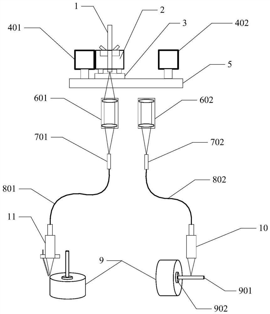
[0030] figure 1 It is a structural schematic diagram of an electrolytic capacitor manufacturing device integrating laser cutting and laser welding according to an embodiment of the present invention. Such as figure 1 As shown, it includes a laser light barrier 1, a laser time-sharing optical system, a slide rail 5, a first beam shaping system 602, a second beam shaping system 603, a fiber coup...


PUM


Abstract

The invention discloses an electrolytic capacitor manufacturing device integrating laser cutting and welding. The electrolytic capacitor manufacturing device comprises a laser light isolator (1), a laser cutting head (10), a laser welding head (11) and a sliding rail (5). The two ends of the sliding rail (5) are provided with a first magnetic attraction locating block (401) and a second magnetic attraction locating block (402) correspondingly, wherein the first magnetic attraction locating block (401) and the second magnetic attraction locating block (402) are opposite in magnetic pole. An electromagnet (2) is arranged in the middle of the sliding rail (5). Currents in the different directions are input, and the electromagnet (2) is located at the welding station or the cutting station. Beam shaping systems, optical fiber couplers and transmission optical fibers are arranged between the sliding rail (5) and the laser welding head (11) as well as between the sliding rail (5) and the laser cutting head (10). The beam shaping systems are located on the bottom of the sliding rail (5) and arranged in the manner of corresponding to the welding station and the cutting station. The invention further discloses an electrolytic capacitor manufacturing method integrating laser cutting and welding. The electrolytic capacitor manufacturing device integrating laser cutting and welding achieves integration of laser cutting and laser welding.

Description

technical field [0001] The invention belongs to the technical field of electronic component manufacturing, and more specifically relates to a manufacturing device and method for an electrolytic capacitor integrating laser cutting and welding. Background technique [0002] Due to the particularity of the space operating environment, extremely high requirements are placed on aerospace electronic components, including electrolytic capacitors. Not only are the components required to be small in size and light in weight, but they are also required to be highly airtight and able to withstand strong shock vibrations and Under the irradiation conditions, it can work stably in a wide temperature range and in a vacuum state, and has a long working life. The modern warfare environment puts forward higher requirements on the performance of electronic devices. [0003] The packaging and sealing of the military electrolytic capacitor case is to protect the inner layer of the device and t...

Claims


Application Information

Patent Timeline
Patent Type & Authority Patents(China)
IPC IPC(8): B23K26/21B23K26/38B23K26/70
CPCB23K26/21B23K26/38B23K26/702
Inventor 张庸
Owner HUBEI SANJIANG AEROSPACE HONGFENG CONTROL
Learn More