Preparation method and equipment of patterned electrostatic chuck

An electrostatic chuck, graphic technology

Active Publication Date: 2018-11-20
BEIJING NORMAL UNIVERSITY
View PDF8 Cites 7 Cited by
  • Summary
  • Abstract
  • Description
  • Claims
  • Application Information

AI Technical Summary

Problems solved by technology

But now for AlN or Al 2 o 3 The manufacture of diamond-like coatings on the surface of ceramic materials has not been seen in the literature, and there are few similar reports

Method used


Image

  • Preparation method and equipment of patterned electrostatic chuck
  • Preparation method and equipment of patterned electrostatic chuck
  • Preparation method and equipment of patterned electrostatic chuck

Examples


preparation example Construction

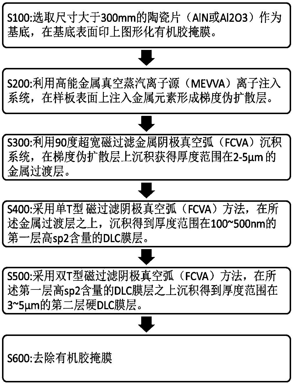
[0056] It should be noted that, in this embodiment, the DLC film is prepared by ion beam technology, and the selected base layer is super-sized (greater than 300mm) AlN or Al 2 o 3 Ceramics. refer to figure 1 , which shows the DLC film preparation method of this embodiment, the preparation method includes the following steps:

[0057] S100: Using super-sized (greater than 300mm) AlN or Al with patterned organic rubber mask printed on the surface 2 o 3 A ceramic sheet is used as the substrate.

[0058] In this step, the screen printing screen is made according to the mask design drawing. The mask glue uses temperature-resistant Japanese Silicon RTV glue, which has a temperature resistance range of 80-400°C, and does not release gas within this range, and at the same time combines with the substrate The strength is not more than 40N. Graphical organic offset printing is applied to the surface of the ceramic sheet by automatic (semi-automatic or manual) screen printing equi...

Embodiment 1

[0088] Embodiment 1: AlN ceramic sheet without DLC coating;

Embodiment 2

[0089] Embodiment 2: AlN ceramic sheet with DLC coating;

[0090] The UMT friction and wear tester is used for the experiment below. The specific settings are: use a SiC standard ball with a diameter of 4mm, the loading force is 200g, the loading time is 5min, 10min, 15min, 30min, 60min, 120min and 180min, and the friction frequency is 2Hz. Back and forth friction.

[0091] refer to Figure 7 , is the comparative data of the friction coefficient of the experimental pieces with DLC coating and without DLC coating.

[0092] from Figure 7 It can be seen that the friction coefficient of aluminum nitride with DLC coating is lower than 0.09, and the lowest reaches about 0.05, while the friction coefficient of aluminum nitride without DLC deposition is relatively large, about 0.8-0.9. The friction coefficient reflects the wear resistance of the material. The smaller the friction coefficient, the better the wear resistance of the film. The friction coefficient of aluminum nitride ...


PUM

PropertyMeasurementUnit
hardnessaaaaaaaaaa
hardnessaaaaaaaaaa
diameteraaaaaaaaaa

Abstract

The invention discloses a preparation method and equipment of a patterned electrostatic chuck. The preparation method comprises the following steps that an ultra-large size (greater than 300 mm) ceramic sheet (AlN or Al2O3) is selected as a substrate, a patterned organic adhesive mask is printed on the substrate, and a high resistivity, high hardness, wear resistance and ion erosion resistance DLCfilm layer is deposited by utilizing an ion beam technology; a deposition method comprises the following steps that a high-energy metal vacuum vapor ion source (MEVVA ) is adopted, a metal element isinjected into the substrate to form a graded pseudo diffusion layer, and then a 90-degree ultra-wide magnetic filtration metal cathode vacuum arc (FCVA) technology is adopted, and a metal transitionlayer is deposited; a single T-shaped magnetic filtration cathode vacuum arc (FCVA) is adopted on the metal transition layer, and a DLC film layer with high sp2 content is obtained through the deposition; and a double-T-shaped magnetic filtration cathode vacuum arc (FCVA) is utilized on the DLC film layer with the high-sp2-content, and a super-hard DLC film layer is obtained through the deposition; and the resistance of the film layer can reach 10-50 megohm, and the hardness can reach 80 Gpa or above. According to the method and the equipment, the electrostatic chuck is enabled to have excellent wear resistance, and the service life is prolonged.

Description

[0001] The invention relates to the technical field of integrated circuit manufacturing, in particular to a method and equipment for depositing a DLC film layer with high resistivity, high hardness, wear resistance and ion erosion resistance on a patterned electrostatic chuck. Background technique [0002] With the recovery of the global economy and the spring of integrated circuit manufacturing, the demand for chucks and electrostatic chucks has risen sharply. The electrostatic chuck is a silicon wafer clamping tool in the semiconductor process. It relies on static electricity to generate adsorption force and adsorb the key clamping parts of the wafer. Its clamping system is generally a sandwich structure: the upper and lower layers are electrodes, and a layer of dielectric is sandwiched between them. The silicon wafer acts as the electrode on the upper surface, and the lower electrode and the dielectric are integrated into one device, which is called an electrostatic chuck. ...

Claims


Application Information

Patent Timeline
Patent Type & Authority Applications(China)
IPC IPC(8): C23C14/02C23C14/04C23C14/06C23C14/32C23C14/48H01L21/683
CPCC23C14/025C23C14/042C23C14/0605C23C14/325C23C14/48H01L21/6831
Inventor 廖斌陈淑年左帅张旭吴先映
Owner BEIJING NORMAL UNIVERSITY
Why Eureka
Try Eureka