
An internal-external heating type pyrolysis device

A double-heating, pyrolysis technology, applied in special forms of dry distillation, direct and indirect heating combined dry distillation, petroleum industry, etc., can solve problems such as increasing application value, shortening reaction cycle, and low efficiency of biomass pyrolysis, achieving Effect of increasing application value, reducing energy consumption, improving pyrolysis efficiency and production efficiency

Inactive Publication Date: 2018-12-07
NORTHWEST A & F UNIV
View PDF4 Cites 1 Cited by
  • Summary
  • Abstract
  • Description
  • Claims
  • Application Information

AI Technical Summary

Problems solved by technology

[0003] In view of the above-mentioned problems and defects in the prior art, the object of the present invention is to provide an internal and external dual-heat pyrolysis device, which solves the technical problem of low biomass pyrolysis efficiency, shortens the reaction cycle, and reduces the production capacity. At the same time, by controlling the air intake, the device can realize multiple functions of one machine and increase the application value. It can not only carry out biomass dry distillation carbonization production, but also biomass gasification and oxygen-limited pyrolysis production. Heating technology to further increase the production efficiency of biomass gasification and oxygen-limited pyrolysis

Method used


Image

  • An internal-external heating type pyrolysis device
  • An internal-external heating type pyrolysis device
  • An internal-external heating type pyrolysis device

Examples


Embodiment Construction

[0015] The beneficial effects of the present invention will be further described below in combination with the specific examples given by the inventor.

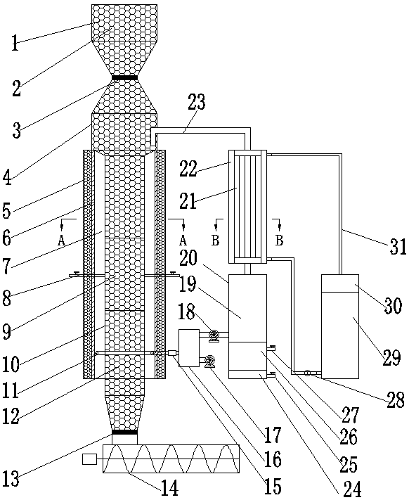
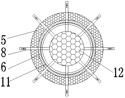
[0016] figure 1 A schematic diagram of the structure of the internal and external double-heating pyrolysis device of the present invention is given, including a furnace body. The upper part of the furnace body is an upper hopper 1 and a raw material settling chamber 4. The lower end of the upper hopper 1 and the upper end of the raw material settling chamber 4 pass through the No. 1 gate valve. 3 connections; figure 2 It is an enlarged view of the A-A view of the furnace body, the outermost layer of the middle section of the furnace body is an insulating layer 5, and the inside thereof is a refractory layer 6, and the upper end of the pyrolysis reaction tube 10 located in the center of the furnace body is connected to the lower end of the raw material settling chamber 4; The lower end of the pyrolysis reaction tube 10 is c...


PUM


Abstract

An internal-external heating type pyrolysis device is disclosed. The device includes a furnace body. The upper section of the furnace body includes a feeding hopper and a raw material settling chamber. The outmost layer of the middle section of the furnace body is a thermally insulating layer inside which a fireproof layer is arranged. The upper end of a pyrolysis reaction tube in the center of the furnace body is connected to the raw material settling chamber, and the lower end of the pyrolysis reaction tube is connected to a charcoal discharging device through a second brake valve. The cavity between the external wall and the fireproof layer is a hearth. A plurality of air pipelines communicating with the pyrolysis reaction tube are mounted in the middle of the furnace body. An annular combuster is mounted at the bottom of the hearth. A fuel gas outlet is connected to the raw material settling chamber, and the other end of the fuel gas outlet is connected to a fuel gas pipeline in acondenser. The fuel gas pipeline is connected to a gas liquid storage tank. A pyrolysis gas storing chamber is connected to a gas mixing chamber through a fuel gas draught fan and a pipeline. The gasmixing chamber communicates with the annular combuster through a flame arrester. A water tank communicates with and is connected to the condenser. The pyrolysis device overcomes a technical problem that the biomass pyrolysis efficiency is low, shortens the reaction period, and reduces production energy consumption.

Description

technical field [0001] The invention belongs to the technical field of biomass pyrolysis reaction, and in particular relates to an internal and external dual-heat type high-efficiency pyrolysis device. Background technique [0002] Biomass pyrolysis refers to the process of molecular cracking of biomass after heating to produce biochar, condensable liquid and combustible gas. There are two most widely used heating methods for biomass pyrolysis in production. One is internal biomass combustion for heat supply. By providing air to the reactor, the biomass is burned to release heat, thereby realizing the heat generation of biomass. crack. When a large amount of air is introduced, the biomass undergoes a gasification reaction, and the resulting product is mainly combustible gas. Since a large amount of nitrogen in the air is mixed into the combustible gas, the calorific value of the combustible gas is generally very low, generally 3~6MJ / Nm 3 , and there are no other high val...

Claims


Application Information

Patent Timeline
IPC IPC(8): C10B53/02C10B51/00
CPCC10B51/00C10B53/02Y02E50/10
Inventor 杨选民邱凌邱洪臣朱琳
Owner NORTHWEST A & F UNIV
Learn More