A method for preparing a membrane electrode using a carbon tube membrane as a carrier

A carbon tube membrane and membrane electrode technology, used in circuits, fuel cells, electrical components, etc., can solve the problems of difficult to completely remove residual impurity ions, difficult to uniform deposition of active metals, and changes in components in the membrane, to overcome the platinum utilization rate. Low effect, shortened proton transport path, and short reduction period

Inactive Publication Date: 2019-01-08
SUZHOU HYDROGINE POWER TECH CO LTD
View PDF4 Cites 3 Cited by
  • Summary
  • Abstract
  • Description
  • Claims
  • Application Information

AI Technical Summary

Problems solved by technology

[0005] The deposition method can make the catalyst in-situ generated on the membrane, and obtain active metal particles and particle size distributions with different structures, sizes and shapes, but it is difficult to completely remove the residua

Method used


Image

  • A method for preparing a membrane electrode using a carbon tube membrane as a carrier
  • A method for preparing a membrane electrode using a carbon tube membrane as a carrier
  • A method for preparing a membrane electrode using a carbon tube membrane as a carrier

Examples


Example Embodiment

[0033] Example 1

[0034] Preparation of cathode electrode pieces:

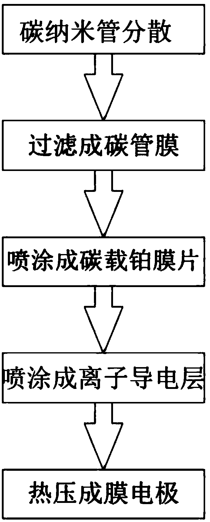
[0035] 1) Take 15 mg of carbon nanotube powder, add 5 g of ethanol, uniformly disperse by ultrasonic wave, and obtain a carbon tube film of 75×75 mm on the gas diffusion layer by means of pressure filtration.

[0036] 2) Fix the carbon tube film on the ultrasonic spraying machine, spray the chloroplatinic acid solution on the carbon tube film, place the sprayed carbon tube film in an atmosphere furnace of a hydrogen atmosphere (ambient temperature is 100° C.) and reduce it for 20min to obtain platinum The loading is 0.4mg / cm 2 carbon-supported platinum diaphragm.

[0037] 3) The perfluorosulfonic acid solution and isopropanol are prepared into an ionic conductor solution with a perfluorosulfonic acid content of 3%, mixed evenly, and the ionic conductor solution is sprayed on the carbon-supported platinum diaphragm by an ultrasonic sprayer, and dried to form Ion conductor layer, the spray loading of the ion...

Example Embodiment

[0043] Example 2

[0044] Preparation of cathode electrode pieces:

[0045] 1) Take 15 mg of carbon nanotube powder, add 5 g of propanol, uniformly disperse by means of high-speed shearing, and obtain a carbon tube film of 75×75 mm on the gas diffusion layer by means of pressure filtration.

[0046] 2) Fix the carbon tube film on the ultrasonic sprayer, spray a mixed solution of chloroplatinic acid and ruthenium trichloride (Pt: Ru=3:1) on the carbon tube film, and place the sprayed carbon tube film in a hydrogen atmosphere ( The ambient temperature is 230 ℃) in the atmosphere furnace for 20min reduction, and the platinum loading is 0.3mg / cm 2 carbon-supported platinum diaphragm.

[0047]3) The perfluorosulfonic acid solution and isopropanol are prepared into an ionic conductor solution with a perfluorosulfonic acid content of 3%, mixed evenly, and the ionic conductor solution is sprayed on the carbon-supported platinum diaphragm by an ultrasonic sprayer, and dried to form ...


PUM


Abstract

The invention relates to a method for preparing a membrane electrode with a carbon tube film as a carrier, comprising the following steps: S1, uniformly dispersing carbon nanotube powder in an alcoholsolvent; 2, uniformly adhere that carbon nanotube powder on the gas diffusion lay through a filtering process to form a carbon tube membrane; S3, uniformly spraying a catalyst precursor containing aplatinum salt solution on the surface of the carbon tube film, and reducing the catalyst precursor so that the platinum salt is reduced into platinum particles to obtain a uniformly dispersed carbon-supported platinum film sheet; S4, uniformly spraying a layer of ionic conductor solution on the carbon-loaded platinum film, drying, and forming an ionic conductive layer on the surface of the platinum particles; 5, place that proton exchange membrane on the ion conductive layer and press the membrane electrode by a hot pressing process. The invention overcomes the problem of low utilization rateof platinum caused by the traditional carbon black as the carrier, realizes the accurate and controllable catalyst and electrolyte layer loading, short reduction cycle, simple equipment requirements,improves production efficiency and reduces cost.

Description

technical field [0001] The invention relates to the field of production and manufacture of membrane electrodes, in particular to a method for preparing membrane electrodes by using carbon tube membranes as carriers. Background technique [0002] A fuel cell is an energy conversion device that directly converts chemical energy into electrical energy, which does not involve the combustion process of a heat engine. Fuel cells have the advantages of environmental friendliness, high energy density, fast start-up at room temperature and high reliability. Compared with other fuel cells, the proton exchange membrane fuel cell (PEMFC) has a relatively low operating temperature and is suitable for use as an electric vehicle and a portable power source. The membrane electrode (MEA) assembly includes a catalyst layer, a gas diffusion layer and a proton exchange membrane, which provide continuous channels of protons, electrons, reactive gases and water for the electrochemical reaction o...

Claims


Application Information

Patent Timeline
IPC IPC(8): H01M8/1067H01M8/1069
CPCH01M8/1067H01M8/1069Y02E60/50Y02P70/50
Inventor 王秀吴丹米诗阳范书琼张晓华朱威
Owner SUZHOU HYDROGINE POWER TECH CO LTD
Why Eureka
Try Eureka