

A method for inter-bed cooling in wet gas sulfuric acid plants
A kind of equipment and technology of sulfuric acid, applied in the direction of steam generation method, separation method, chemical instrument and method using heat carrier, etc., can solve the problem of unspecified type of interbed cooler
- Summary
- Abstract
- Description
- Claims
- Application Information
AI Technical Summary
Problems solved by technology
Method used
Image

Examples
Embodiment 1
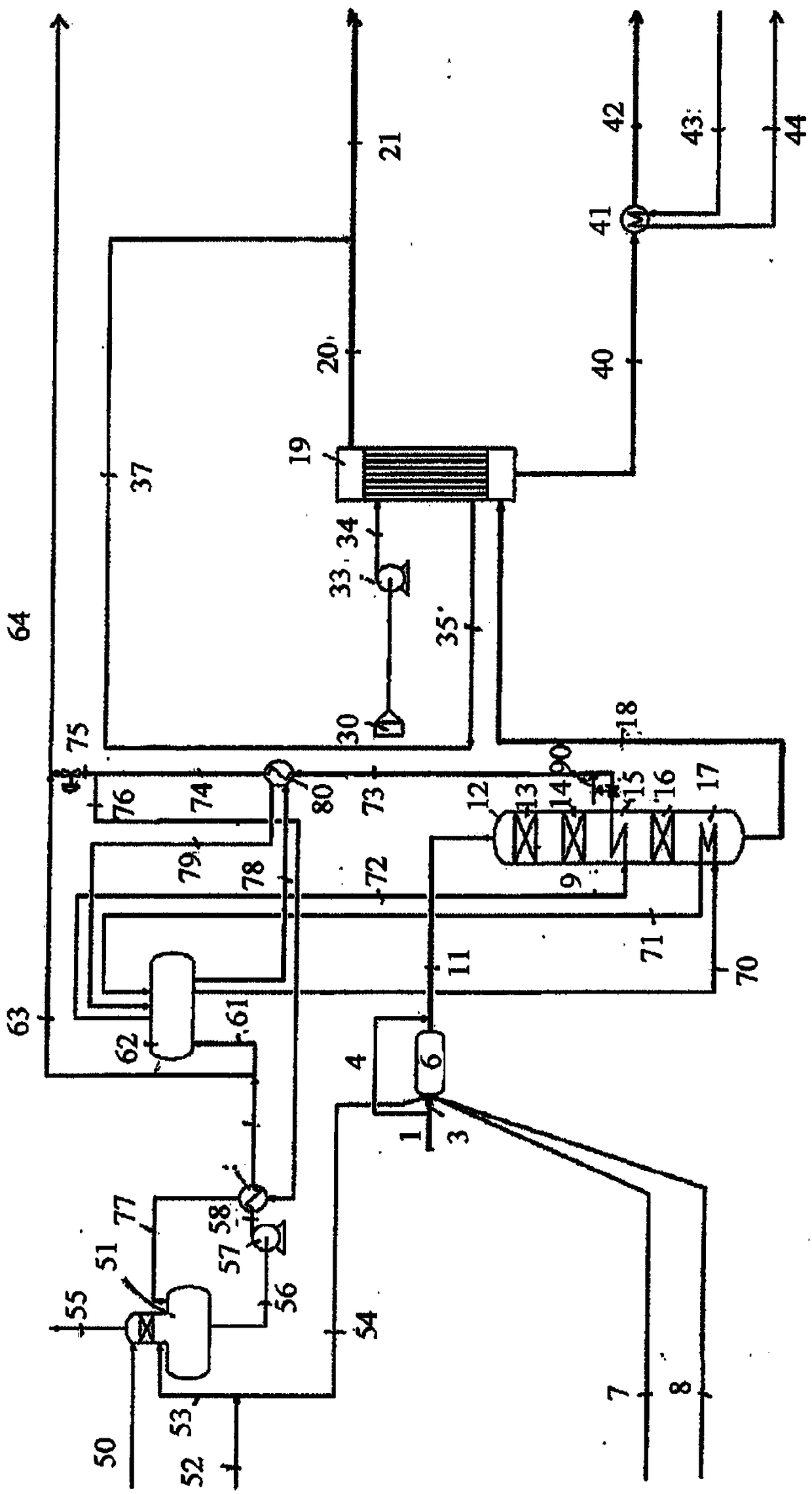
[0051] In this example, will contain 0.38vol% CS 2 , 0.36vol%H 2 S and the rest is 30,000Nm of ambient air 3 / h viscose tail gas respectively in figure 1 and 2 shown in the WSA device processing. Additionally, 400kg / h molten sulfur (7) is incinerated to facilitate sulfuric acid production and add supplementary heat to the thermal burner, and 80kg / h low pressure steam (54) is used for atomization of molten sulfur. Natural gas (8) is added to the hot burner to achieve a temperature of 850°C in the hot burner (6). In the catalytic oxidation of CS 2 and H 2 After S, the resulting process gas contains 2-3 vol% SO 2 .
[0052] In this example, the sulfuric acid dew point temperature in the process gas stream (18) at the inlet of the WSA condenser (19) is only 238°C. Consequently, the inlet temperature of the WSA condenser as well as the saturated steam temperature in the steam system have been reduced to 270°C and 255°C, respectively, compared to the maximum values of 290°C...
Embodiment 2
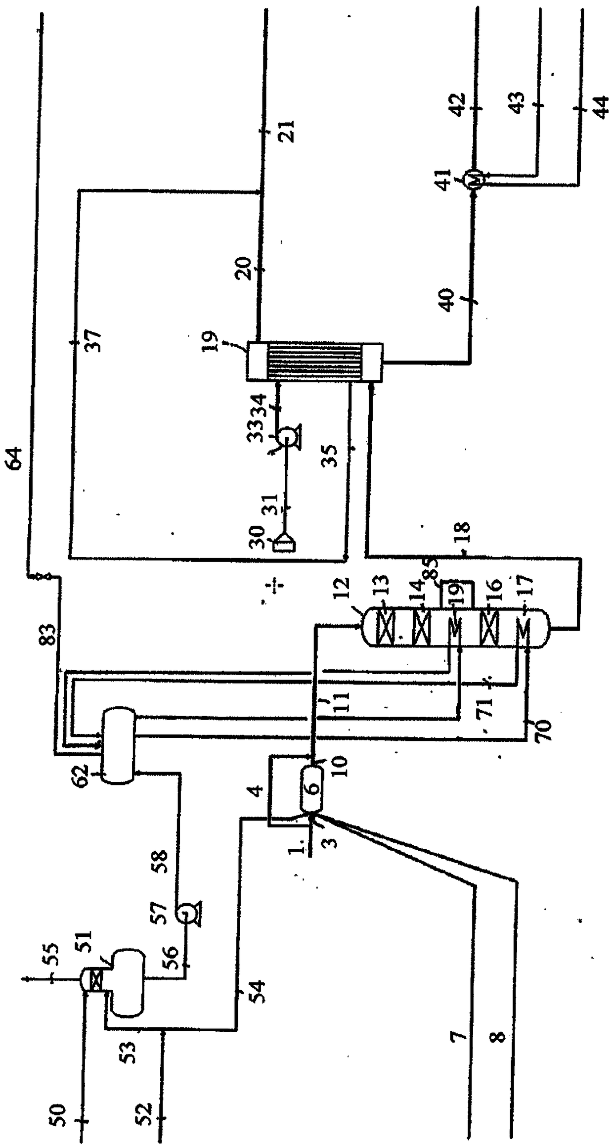
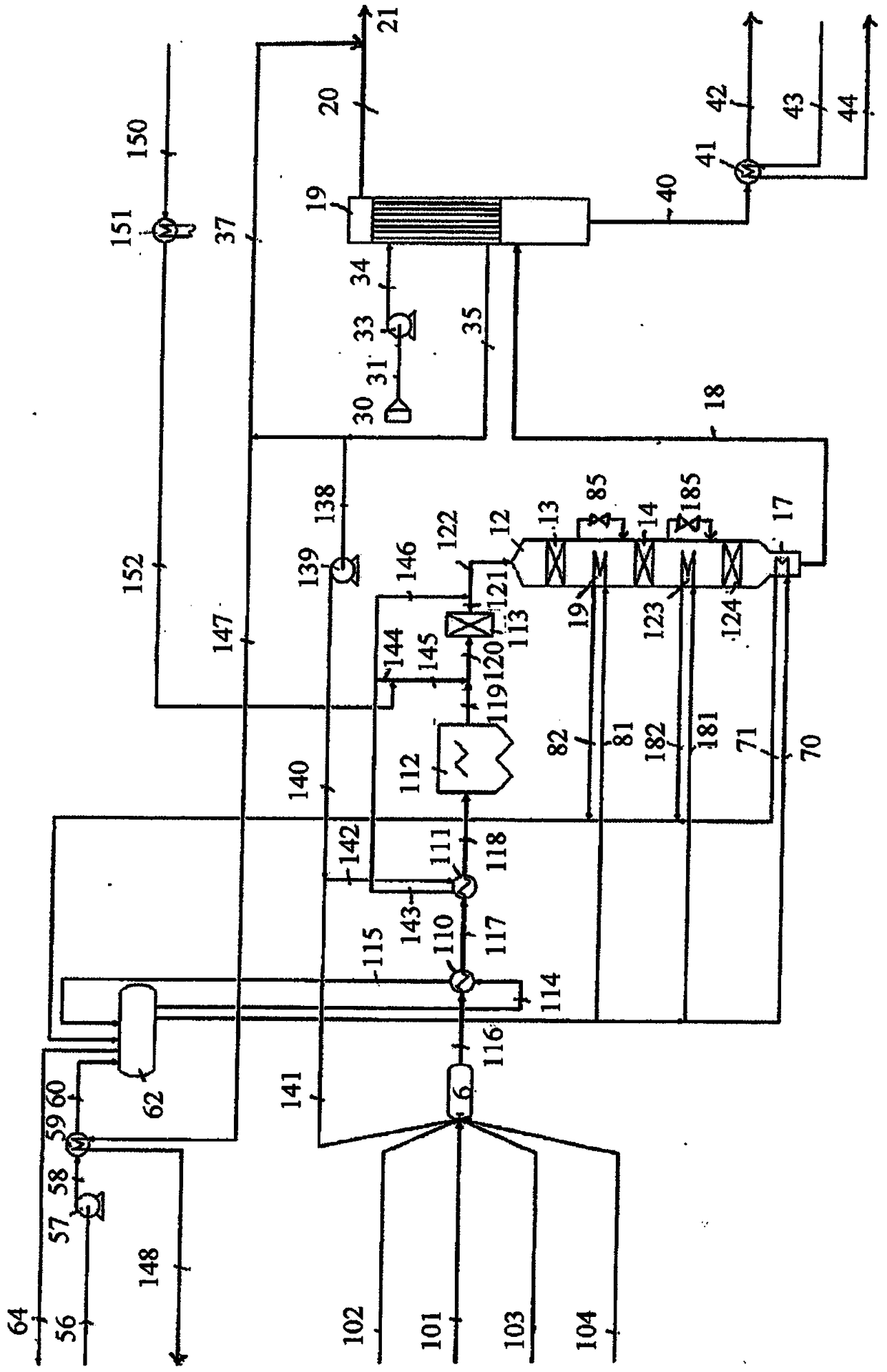
[0064] image 3 Another embodiment of the application of the invention is shown. In this example, the WSA device is configured to make 2 SO 4 , 4wt%H 2 O, 0.3wt%SO 2 Regenerated with 100MTPD waste sulfuric acid (101) of 5.7wt% sulfur-containing hydrocarbons. The spent acid (101 ) is atomized into the thermal burner (6) using atomizing air (102) and the heat input required to maintain the burner temperature of ~1000°C is supplied by burning gas. Hot combustion air is supplied via line (141). In the thermal burner (6), the spent acid is degraded to SO 2 、H 2 O and CO 2 . The process gas (116) from the burner is sent to the waste heat boiler (110) where it is cooled. In a further cooling step, the process gas is cooled in an air preheater (111). The process gas then enters an electrostatic precipitator (112) where dust, mainly from corrosion products of the upstream alkylation process, is removed.
[0065] Optionally, if needed to reduce NOx emissions, an SCR reactor ...
Embodiment 3
[0073] Figure 4 Another embodiment of the application of the invention is shown. In this embodiment, the WSA plant is configured to treat sour gas. will contain 30vol% H 2 S, 0.4vol%CO, 0.1vol%H 2 , 700ppmv COS and the rest is CO 2The acid gas is sent to the hot burner (6) via pipeline (105). In the hot burner, the acid gas is oxidized to SO 2 , CO 2 and H 2 O. Combustion and SO 2 Oxygen required for oxidation is sent to the burner in the form of hot air via line (141). Process gas from the burner enters the waste heat boiler (110) via line (116). In the waste heat boiler, the process gas is cooled to SO 2 Converter inlet temperature. depends on NO x emission requirements, the process gas can then be subjected to NO in the SCR reactor (113) x reduction, and the ammonia required for the SCR reaction is added to the process gas via line (165). Then, include SO 2 The process gas (122) enters SO 2 Converter (12), similar to that in Example 2, the SO 2 The conver...
PUM
 Abstract
Description
Claims
Application Information