Eureka AIR delivers breakthrough ideas for toughest innovation challenges, trusted by R&D personnel around the world.

Preparation method of surface coating of zirconium alloy cladding and surface coating

A surface coating, zirconium alloy technology, applied in metal material coating process, coating, ion implantation plating and other directions, can solve the problems of radioactive material leakage, cladding tube embrittlement, zirconium alloy corrosion, etc. Low technology, high temperature stability, dense and uniform coating effect

Active Publication Date: 2019-04-05
STATE POWER INVESTMENT CORP RES INST
View PDF2 Cites 5 Cited by
  • Summary
  • Abstract
  • Description
  • Claims
  • Application Information

AI Technical Summary

Problems solved by technology

However, due to the high temperature environment, especially in the loss of coolant accident or loss of water accident (LOCA, Loss of Coolant Accident) conditions, the zirconium alloy on the water side will undergo severe corrosion and hydrogen absorption, resulting in brittle fracture of the cladding tube Phenomenon
For example, in the Fukushima accident, due to the loss of water in the core and the temperature rising to about 1200°C, the intense heat release of the fuel rod zirconium alloy cladding and water vapor will greatly accelerate the process of the accident, which not only directly releases a large amount of heat, but also causes the fuel element to explode rapidly. As the temperature rises, a large amount of hydrogen is also produced, causing serious consequences such as hydrogen explosion and leakage of radioactive substances.

Method used


Image

  • Preparation method of surface coating of zirconium alloy cladding and surface coating
  • Preparation method of surface coating of zirconium alloy cladding and surface coating
  • Preparation method of surface coating of zirconium alloy cladding and surface coating

Examples


preparation example Construction

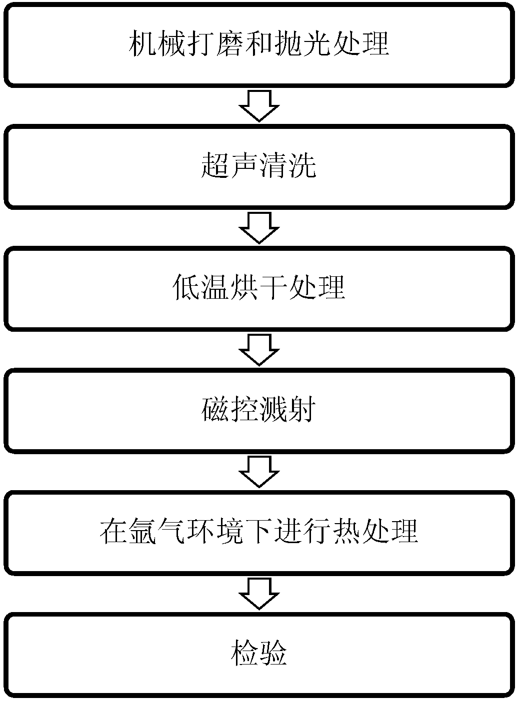
[0040] Specifically, the preparation method includes the following steps (combining figure 1 ):

[0041]A zirconium alloy substrate is provided, and the zirconium alloy substrate can be a block substrate and a tubular substrate;

[0042] The zirconium alloy block and tubular substrates are mechanically ground and polished. First, the zirconium alloy substrates are polished several times with 80-mesh to 5000-mesh sandpaper, and then polished, and then placed in a solution composed of acetone and deionized water. Wash for 5-10 minutes, and dry at low temperature;

[0043] Fix the sample (zirconium alloy substrate) after the above treatment in the fixture of the magnetron sputtering apparatus, adjust the target base distance between 40-80mm, and pump the background vacuum to the highest value that the equipment can reach 10 -6 The order of magnitude of Pa. The temperature of the chamber is controlled at room temperature (20°C) to 600°C, and the chamber pressure is adjusted wit...

no. 1 example

[0054] First Example: Single Carbide Coating

[0055] First prepare the zirconium alloy bulk and tubular substrates, wherein the bulk substrate is a zirconium alloy plate with a size of 20mm×20mm×5mm, and the tubular substrate is a zirconium alloy tube with a size of Φ9.5mm, a thickness of 0.57mm and a length of 200mm. For the above zirconium alloy The substrate is mechanically ground and polished. First, the zirconium alloy substrate is polished several times with 80-mesh to 5000-mesh sandpaper, then polished, and then ultrasonically cleaned in a solution composed of acetone and deionized water for 10 minutes, and then dried at a low temperature. deal with.

[0056] Fix the sample after the above treatment in the fixture of the magnetron sputtering apparatus, adjust the base distance of the target at 60 mm, and pump the background vacuum to 10 -3 Pa order of magnitude. The chamber temperature is controlled from room temperature to 400°C. Use argon to adjust the air pressur...

no. 2 example

[0059] Second Example: Composite Carbide Coating

[0060] First prepare the zirconium alloy bulk and tubular substrates, wherein the bulk substrate is a zirconium alloy plate with a size of 20mm×20mm×5mm, and the tubular substrate is a zirconium alloy tube with a size of Φ9.5mm, a thickness of 0.57mm and a length of 200mm. For the above zirconium alloy The substrate is mechanically ground and polished. First, the zirconium alloy substrate is polished several times with 80-mesh to 5000-mesh sandpaper, then polished, and then ultrasonically cleaned in a solution composed of acetone and deionized water for 10 minutes, and then dried at a low temperature. deal with.

[0061] Fix the sample after the above treatment in the fixture of the magnetron sputtering apparatus, adjust the target base distance to 80mm, and pump the background vacuum to 10 -4 Pa. The chamber temperature is controlled from room temperature to 400°C. Use argon to adjust the air pressure of the chamber so tha...


PUM

PropertyMeasurementUnit
Thicknessaaaaaaaaaa

Abstract

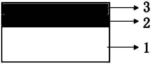
The invention provides a preparation method of a surface coating of a zirconium alloy cladding, and further provides the surface coating. The preparation method is characterized in that a carbide target material is adopted to form a carbide coating on a zirconium alloy matrix. The preparation method comprises the steps that mechanical grinding and polishing treatment are carried out on the zirconium alloy matrix; the zirconium alloy matrix is placed in a solution composed of acetone and deionized water to be subjected to ultrasonic cleaning; the zirconium alloy matrix is subjected to low-temperature drying treatment; the carbide target material is subjected to sputtering sintering through a radio frequency magnetron sputtering method, sputtering power is 1200 W or below, the bias range is0 V to 1000 V, and a carbide coating is formed; the zirconium alloy matrix on which the carbide coating is formed is taken out of a magnetron sputtering instrument, and thermal treatment is carried out under an argon environment for 1 h to 3 h at the temperature of 500 DEG C to 700 DEG C; and the zirconium alloy cladding on which the carbide coating is formed is subjected to inspection. Accordingto the preparation method of the surface coating of the zirconium alloy cladding, corrosion resistance and oxidization resistance of the zirconium alloy cladding can be improved.

Description

technical field [0001] The invention relates to the technical field of surface treatment, in particular to a method for preparing a surface coating of a zirconium alloy cladding and a surface coating. Background technique [0002] Nuclear fuel cladding is the first protective barrier of a nuclear reactor, and its safety is of paramount importance. As far as its working condition is concerned, because one side is close to the high-temperature nuclear fuel pellet part, and the other side is in contact with the coolant under high temperature and high pressure (for example, the temperature is between 280-350°C and the pressure is between 10-16MPa Inter-) contact, so during use, on the side close to the core block, the expanded core block will generate strain with the cladding (PCI, Pellet-Cladding interaction), resulting in stress corrosion cracking (SCC, Stress Corrosion Cracking) of the cladding ), while on the side close to the coolant, it will be corroded by the coolant. T...

Claims


Application Information

Patent Timeline
IPC IPC(8): C23C14/35C23C14/06G21C3/07
CPCG21C3/07C23C14/0635C23C14/35Y02E30/30
Inventor 刘艳红王晓婧冯硕李怀林夏海鸿
Owner STATE POWER INVESTMENT CORP RES INST
Why Eureka
Eureka Blog
Learn More