Perovskite solar cell and preparation method thereof

A solar cell and perovskite technology, applied in the field of solar cells, can solve the problems of increased preparation cost, time-consuming consumables, extra energy consumption, etc., and achieves the effect of eliminating Schottky barrier, saving process cost, and good adaptability

Active Publication Date: 2019-05-17
UNIV OF ELECTRONICS SCI & TECH OF CHINA
View PDF3 Cites 7 Cited by
  • Summary
  • Abstract
  • Description
  • Claims
  • Application Information

AI Technical Summary

Problems solved by technology

Compared with p-layer materials, these commonly used n-layer materials face similar problems: because these metal oxides are insoluble in various solvents, in order to obtain a uniform and dense electron transport layer, we can only use sputtering Or complex and difficult large-scale preparation methods such as electron beam evaporation, or first prepare metal chlorides or nitrates that are easily soluble in traditional solvents, and then convert them into metal oxides by oxidation methods such as annealing, and this preparation method will Cause waste of materials and additional energy consumption, which increases the cost of preparation
[0004] In order to solve the problems of high temperature and difficulty in large-area preparation of the metal oxide electron transport layer, current researchers have made various attempts: such as making the oxide semiconductor into a suspension and then spin-coating or The low-temperature annealing process is studied by using the low-temperature crystallinity of tin oxide, but no matter which method can avoid the two core steps of preparing the precursor and enhancing the crystallinity, this makes the preparation process consumable and time-consuming
Another more direct option is to abandon the electron transport layer and directly contact the perovskite light absorbing layer with FTO, but this will inevitably affect the efficiency, such as the pinhole defect of the perovskite film. The resulting leakage current will be amplified on devices without an electron transport layer, resulting in a rapid drop in open circuit voltage and fill factor; direct contact between a large number of defects in the electrode and the light absorbing layer will cause a large number of carriers to recombine at the interface, Reduce the conversion efficiency of the battery; what is more serious is that the energy band structure of the electrode itself does not match the light absorption layer of the perovskite, the electrode itself cannot play the role of electron extraction played by the electron transport layer, and even in the electrode-perovskite A Schottky barrier is formed at the interface, which prevents the transport of electrons from the light-absorbing layer to the electrode
[0005] At present, further improvement methods include: increasing the grain size of the perovskite light-absorbing layer to reduce the pinhole defects of the perovskite (Yu H, Ryu J, Lee J W, et al. Large Grain-Based Hole-Blocking Layer- FreePlanar-Type Perovskite Solar Cell with Best Efficiency of 18.20%[J].ACSapplied materials&interfaces, 2017,9(9):8113-8120), or modify the perovskite layer to make the light-absorbing layer transparent and conductive Electrode direction matching (Ke W, Fang G, Wan J, et al.Efficienthole-blocking layer-free planar halide perovskite thin-film solar cells[J].Nature communications,2015,6:6700.MLA), in addition Wai Jang et.al electrochemically etched the FTO (fluorine-doped tin oxide) electrode to increase its specific surface area to improve efficiency (Ke W, Fang G, Wan J, et al. Efficient hole-blocking layer-free planar halide perovskite thin-film solar cells[J].Nature communications,2015,6:6700), but none of these methods involves modifying FTO to make it more closely match the energy band of the target perovskite

Method used


Image

  • Perovskite solar cell and preparation method thereof
  • Perovskite solar cell and preparation method thereof
  • Perovskite solar cell and preparation method thereof

Examples


Embodiment 1

[0036] Step 1. Perform plasma treatment on FTO, the specific steps are:

[0037] Step 1.1. Place the FTO substrate material in acetone, absolute ethanol and deionized water for 20 minutes, and then dry it with a nitrogen gun for later use;

[0038] Step 1.2. Place the FTO substrate material cleaned in step 1.1 on the metal lower plate in the plasma chamber, the distance between the metal plates is 34mm, the upper plate is connected to 27MHz RF power supply, and the lower plate is connected to 13.56MHz RF power supply;

[0039] Step 1.3. Vacuum the plasma chamber to a vacuum of 10 -3 Pa, then feed oxygen with a purity of 99.999%, and control the oxygen flow rate so that the working pressure in the chamber is 15Pa;

[0040] Step 1.4. Set the discharge power of the upper plate to 180W, the discharge power of the lower plate to 44W, discharge the upper and lower plates at the same time, and perform plasma treatment on the FTO substrate for 15 minutes, so that the F element on the ...

Embodiment 2

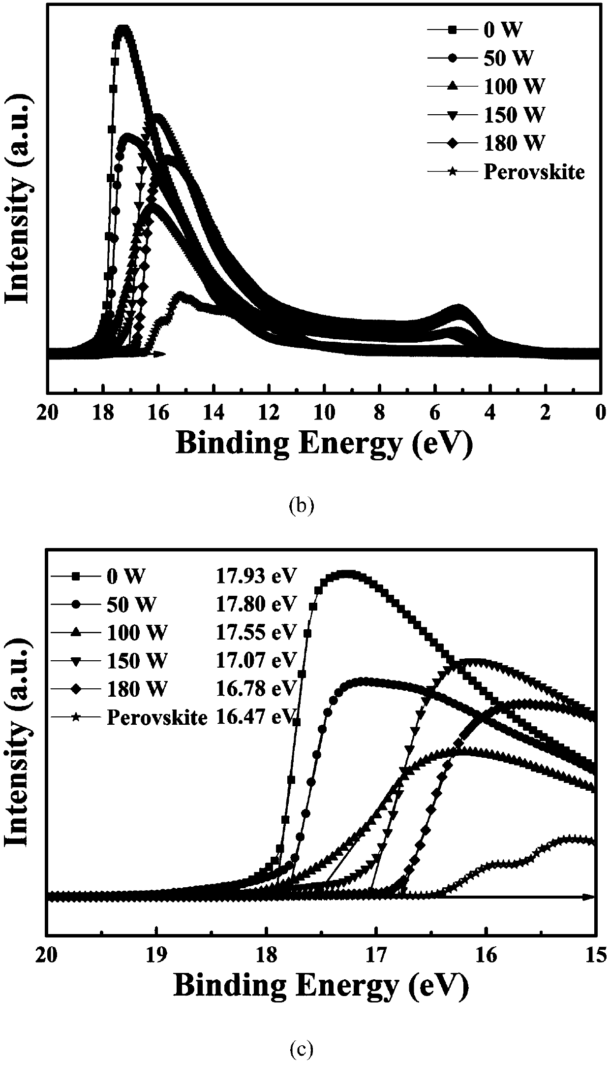
[0046] The perovskite battery was prepared according to the steps of Example 1, only the discharge power of the upper plate in Step 1 was adjusted to 50W, 100W or 150W, and other steps were kept unchanged. The ultraviolet photoelectron spectrum of the perovskite solar cell prepared in this embodiment is as follows figure 2 As shown, the device J-V performance graph is shown in image 3 shown.

Embodiment 3

[0048] The perovskite battery was prepared according to the steps in Example 1, only the plasma treatment time in step 1.4 was adjusted to 30 min, and the other steps remained unchanged.


PUM


Abstract

The invention provides a perovskite solar cell and a preparation method thereof, and belongs to the technical field of solar cells. The solar cell is not provided with an electron transmission layer directly adopts an i-p structure, abandons a traditional electron transmission layer, is replaced with a modified FTO (Functional Test Objective), and utilizes the FTO to realize the function of the traditional electron transmission layer. The preparation method for the solar cell is characterized in that the FTO is subjected to modified processing to realize the continuous control of an FTO energylevel energy band, a Schottky barrier generated when an FTO-perovskite interface is in contact is successfully eliminated, so that the FTO has the characteristics of the electron transmission layer,the efficiency of the perovskite solar cell without the electron transmission layer is improved, and 1 / 3 of technical cost is saved. In addition, the environment temperatures in all preparation stepsto which the invention relates do not exceed 200DEG C, and therefore, the perovskite solar cell exhibits good adaptation with a plastic base flexible substrate.

Description

technical field [0001] The invention belongs to the technical field of solar cells, and in particular relates to a perovskite solar cell and a preparation method thereof. Background technique [0002] In recent years, organic-inorganic hybrid perovskite solar cells have attracted extensive attention due to their excellent photoelectric performance and low cost, and their photoelectric conversion efficiency jumped from 3.8% in 2009 to over 23% in 2018. The rapid improvement of the photoelectric conversion efficiency of perovskite solar cells has benefited from the progress of the preparation method of the perovskite film on the one hand, and the research progress of the perovskite carrier transport layer on the other hand. [0003] Perovskite solar cells often use an n-i-p or p-i-n sandwich structure, where n is the electron transport layer, i is the perovskite light absorption layer, p is the hole transport layer, and n and p can be collectively referred to as calcium The c...

Claims


Application Information

Patent Timeline
Patent Type & Authority Applications(China)
IPC IPC(8): H01L51/42H01L51/00H01L51/48
CPCY02E10/549Y02P70/50
Inventor 熊杰孙浩轩晏超贻杜新川黄建文邬春阳戴丽萍
Owner UNIV OF ELECTRONICS SCI & TECH OF CHINA
Why Eureka
Try Eureka