Supercharge Your Innovation With Domain-Expert AI Agents!

Partial redox removal method for NOX from boiler flue gas and removal device

A boiler flue gas removal technology, applied in separation methods, chemical instruments and methods, gas treatment and other directions, can solve the problems of poor reduction effect, low catalyst quantum yield, difficult to control oxidation degree, etc., and achieve high temperature resistance and corrosion resistance. Strong ability, improve the photocatalytic oxidation speed, reduce the effect of oxidation residence time

Active Publication Date: 2019-07-12
山东默锐环境产业股份有限公司
View PDF10 Cites 0 Cited by
  • Summary
  • Abstract
  • Description
  • Claims
  • Application Information

AI Technical Summary

Problems solved by technology

After most of NO is oxidized (also known as NO full oxidation), it is absorbed by lye. To meet the discharge standard, it needs to consume more oxidant, which is expensive and hinders industrial application.
There are two ways to reduce the cost of this technology: one is to choose cheap oxidants (such as H 2 o 2 or NaClO), but the oxidation effect of NO is limited, and auxiliary means such as catalysis are needed, and the development of catalysts has not been able to break through SO 2 and water vapor poisoning lead to catalytic deactivation; the second is to implement quantitative oxidation of NO (i.e. partial oxidation of NO) instead of pursuing high NO x degree of oxidation (NO x Medium NO 2 ratio) to save oxidants, and then control NO and NO by adjusting the degree of oxidation 2 The ratio of urea, sodium sulfite, and sodium bisulfite is used as a reducing agent for reduction and denitrification, which reduces costs and ensures high denitrification efficiency. However, this technology has the problem that the degree of oxidation is difficult to control and the reduction effect is poor.
[0004] It has been 50 years since Japanese scientists Fujishima and Honda discovered photocatalysis, and the development of its application is still going on. Among many photocatalysts, TiO 2 Photocatalyst has excellent properties such as high oxidation activity, stable activity, and not easy to decompose itself. However, so far, its application in the oxidation treatment of exhaust gas is still greatly restricted. At present, there are still several problems restricting the application of photocatalytic technology in exhaust gas treatment. The industrial application of the catalyst, including the low quantum yield of the catalyst, the low utilization rate of visible light, and the difficulty of separating nanocatalysts, etc.

Method used


Image

  • Partial redox removal method for NOX from boiler flue gas and removal device
  • Partial redox removal method for NOX from boiler flue gas and removal device
  • Partial redox removal method for NOX from boiler flue gas and removal device

Examples


Embodiment 1

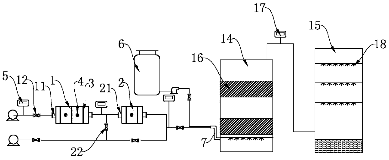
[0053] (1) Photocatalytic oxidation: The boiler flue gas enters the two-stage photocatalytic oxidation device in series respectively, and the photocatalytic oxidation is carried out in sequence. The first-stage photocatalytic oxidation device is equipped with three mesh plates loaded with photocatalysts along the gas flow direction ; In the second-stage photocatalytic oxidation device, there are two loaded nano-Pd / TiO along the direction of gas flow. 2 50W LED lights are arranged between the mesh panels. The residence time of boiler flue gas in the first-stage photocatalytic oxidation device is 15s; the residence time of boiler flue gas in the second-stage photocatalytic oxidation device is 10s. NO in the flue gas after the first stage photocatalytic oxidation X The degree of oxidation is 75%, and the NO in the flue gas after the second stage photocatalytic oxidation X The degree of oxidation is 50%. According to the inlet oxidation degree and outlet gas oxidation degree of...

Embodiment 2

[0058] (1) Photocatalytic oxidation: The boiler flue gas enters the two-stage photocatalytic oxidation device in series respectively, and the photocatalytic oxidation is carried out in sequence. The first-stage photocatalytic oxidation device is equipped with three mesh plates loaded with photocatalysts along the gas flow direction ; In the second-stage photocatalytic oxidation device, there are two loaded nano-Pd / TiO along the direction of gas flow. 2 50W LED lights are arranged between the mesh panels. The residence time of boiler flue gas in the first-stage photocatalytic oxidation device is 18s; the residence time of boiler flue gas in the second-stage photocatalytic oxidation device is 12s. NO in the flue gas after the first stage photocatalytic oxidation X The degree of oxidation is 80%, and the NO in the flue gas after the second stage photocatalytic oxidation X The degree of oxidation is 49%. According to the inlet oxidation degree and outlet gas oxidation degree of...

Embodiment 3

[0063] (1) Photocatalytic oxidation: The boiler flue gas enters the two-stage photocatalytic oxidation device in series respectively, and the photocatalytic oxidation is carried out in sequence. The first-stage photocatalytic oxidation device is equipped with three mesh plates loaded with photocatalysts along the gas flow direction ; In the second-stage photocatalytic oxidation device, there are two loaded nano-Pd / TiO along the direction of gas flow. 250W LED lights are arranged between the mesh panels. The residence time of boiler flue gas in the first-stage photocatalytic oxidation device is 10s; the residence time of boiler flue gas in the second-stage photocatalytic oxidation device is 8s. NO in the flue gas after the first stage photocatalytic oxidation X The degree of oxidation is 70%, and the NO in the flue gas after the second stage photocatalytic oxidation X The degree of oxidation is 50%. According to the inlet oxidation degree and outlet gas oxidation degree of e...


PUM


Abstract

The invention discloses a partial redox removal method for NOX from boiler flue gas and a removal device. The method comprises the following steps: (1) enabling the boiler flue gas to separately enterat least two stages of mutual-series-connected photocatalytic oxidation devices for photocatalytic oxidation sequentially, wherein the degree of oxidation of the NOX in the flue gas subjected to thephotocatalytic oxidation is 45% to 50%; (2) subjecting the flue gas subjected to the catalytic oxidation and a reduction solution to instant pressurizing and flue gas atomizing in a mixed feeder, so as to obtain atomized flue gas; (3) enabling the atomized flue gas to enter a reduction denitrating column, carrying out reduction denitration by denitration catalyzing fillers, and then, exhausting the flue gas from a top; and (4) enabling the flue gas come from the top of the reduction denitrating column to enter a desulfurizer, carrying out desulfurization by a sprinkling desulfurization solution, and then, exhausting the flue gas after reaching standards. According to the method and the device, the boiler flue gas separately enters the at least two stages of mutual-series-connected photocatalytic oxidation devices for photocatalytic oxidation sequentially, so that the rate of photocatalytic oxidation is increased, the degree of oxidation of each stage is controlled accurately, and a good reduction denitration effect is guaranteed.

Description

technical field [0001] The invention relates to the technical field of industrial waste gas treatment, in particular to a NO X Redox removal technology. Background technique [0002] At present, the nitrogen oxides NO emitted into the atmosphere by the industrial production process x NO and NO 2 Mainly, they are the main precursors of acid rain and smog, which seriously endanger the ecological environment and human health. Nitric oxide (NO) in boiler flue gas accounted for total nitrogen oxides (NO x ) above 95%, NO is not easily absorbed in water or lye, and nitrogen dioxide (NO 2 ) is easily soluble in water and easy to remove, so the main problem of flue gas denitrification is to remove NO. [0003] According to NO and NO in flue gas 2 Different denitrification methods can be used for different content: NO 2 Mainly NO x Exhaust gas is mainly absorbed and purified; while NO mainly consists of NO x Exhaust gases can reduce NO to harmless N 2 , this process is divi...

Claims


Application Information

Patent Timeline
IPC IPC(8): B01D53/75B01D53/56B01D53/78B01D53/50
CPCB01D53/502B01D53/56B01D53/75B01D2251/304B01D2255/1023B01D2255/20707B01D2255/802B01D2258/0283
Inventor 徐永生王志孝杨建伟刘玉辉孙广金魏雪花张海涛王彦玲
Owner 山东默锐环境产业股份有限公司
Features
  • R&D
  • Intellectual Property
  • Life Sciences
  • Materials
  • Tech Scout
  • Unparalleled Data Quality
  • Higher Quality Content
  • 60% Fewer Hallucinations
Learn More