
Large splicing type plastic inspection well chamber, forming processing equipment and forming method

A technology of plastic inspection wells and large-scale splicing, applied in artificial islands, water conservancy projects, infrastructure projects, etc., can solve the problems of poor welding strength, affecting the welding strength and welding quality, and large size of injection molds. Seam joint strength, improve the quality of laser welding, improve the effect of mechanical strength

Inactive Publication Date: 2019-07-26
CHANGZHOU COLLEGE OF INFORMATION TECH
View PDF13 Cites 0 Cited by
  • Summary
  • Abstract
  • Description
  • Claims
  • Application Information

AI Technical Summary

Problems solved by technology

[0003] One-time integral injection molding is a traditional molding method for plastic inspection wells. However, it is extremely difficult to use one-time integral injection molding for large plastic inspection well chambers with a wall thickness of 15-20mm, a diameter of 1500-2000mm, and a height of 1000-2000mm. The size of the mold is large, and it is difficult to demould the mold of the well chamber and the rib plate. Moreover, a super-large injection molding machine is required to meet the injection molding process of the well chamber. The manufacturing cost of the injection mold and the injection molding machine equipment are high, and the production efficiency is low.
Application numbers 201810097724.0 and 201610885926.2 provide the molding processing device and molding method of straight-through plastic inspection wells, but the outer wall of straight-through plastic inspection wells is not provided with reinforcing ribs, which are only suitable for plastic inspection wells with a diameter of less than 1000mm.
Application number 201510711017.2 provides an integrated anti-settling valve inspection well, which is processed by rotational molding process, but the rotational molding process has low production efficiency and is not suitable for mass production
[0004] At present, the combination methods of plastic welding are mainly hot plate welding, hot melt winding, ultrasonic welding, melt filling and chemical bonding, etc. For large plastic inspection wells with complex structures and large sizes, these welding combination methods have large welding deformation and welding problems. Problems such as poor strength, poor weld sealing, low production efficiency, etc.
[0005] Invention patent application numbers: 201810097725.5, 201810098632.4, 201810098631.X, 201810097724.0, 201810096336.0, which provide a variety of laser combination molding methods for large plastic inspection wells. Multiple parts in the form of splicing and connection, each part is combined and connected by laser welding to form an inspection well, but since the welding surface of each component, that is, the weld seam, is on the inlaid butt joint surface of each component, the inlaid butt joint surface, that is, the weld seam, is in the inspection well Inside the wall, it forms an included angle with the wall of the inspection well. Since the weld cannot be equidistantly parallel to the outer wall of the inspection well, when laser welding is performed, the laser welding adopts the transmission welding method. Influenced by factors such as beam scattering and inspection well material absorption, when the laser beam passes through the uneven and equidistant inspection well wall, the spot energy distribution of the laser beam irradiating the weld is uneven, so the heat distribution of the weld absorbed by the laser conversion is uneven Even, the uneven temperature distribution of the weld affects the joint strength and welding quality of the weld, and reduces the mechanical strength of the inspection well
In addition, during laser welding of large plastic inspection wells, due to the large welding length, width and welding area, it has been difficult to reasonably solve the problems of welding seam positioning and clamping mechanism design for large plastic inspection wells.

Method used


Image

  • Large splicing type plastic inspection well chamber, forming processing equipment and forming method
  • Large splicing type plastic inspection well chamber, forming processing equipment and forming method
  • Large splicing type plastic inspection well chamber, forming processing equipment and forming method

Examples


Embodiment Construction

[0045] In order to enable those skilled in the art to better understand the technical solution of the present invention, the technical solution of the present invention will be further described below in conjunction with the accompanying drawings and embodiments.

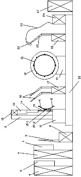
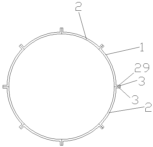
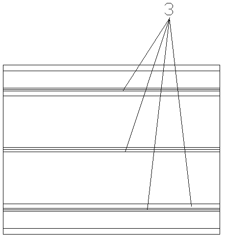
[0046] Embodiment: refer to attached Figure 2-7 As shown, the large-scale spliced ​​plastic inspection well chamber is a cylindrical structural member welded by 8 coaxial fan-shaped parts in sequence. The fan-shaped parts include black fan-shaped piece 1 and white fan-shaped piece 2. The cylindrical structural member is welded alternately by black sector 1 and white sector 2, and the two ends of each black sector 1 and each white sector 2 are integrally formed with outwardly protruding flanging 3, Flange 3 is used for welding butt joint of black sector 1 and white sector 2;

[0047] Specifically, the bottom side of a white fan-shaped piece 2 and the upper side of a black fan-shaped piece 1 are butted to form a wel...


PUM

PropertyMeasurementUnit
thicknessaaaaaaaaaa
diameteraaaaaaaaaa
heightaaaaaaaaaa

Abstract

The invention discloses a large splicing type plastic inspection well chamber, forming processing equipment and a forming method. The well chamber is formed by splicing and combining sector pieces with the number of 8-16, the sector pieces are subjected to extrusion molding and forming processing, the sector pieces are connected in an ultrasonic spot welding mode to serve as a well chamber, and then laser transmission and welding are carried out to splice welding joints of the sector pieces. The forming and processing equipment comprises plastic extruding equipment, a plastic extruding mold, arobot, a mechanical arm, a conveying belt, a well chamber positioning control mechanism, an ultrasonic welding system, a laser welding system, a control system and the like. The large splicing type plastic inspection well chamber, the forming processing equipment and the forming method are used for realizing modular and automatic mass production of the large plastic inspection well chamber; the mold structure is simplified, and the design and manufacturing difficulty of the mold is reduced; and the quality of the laser welding joints is improved, and the connection reliability and the sealingproperty of the well chamber are enhanced.

Description

technical field [0001] The invention relates to the field of forming and processing of large plastic inspection wells, in particular to a large spliced ​​plastic inspection well chamber, forming processing equipment and a forming method. Background technique [0002] In the construction of municipal water supply and drainage pipe network systems, the market demand for large plastic inspection wells such as valve wells and drop wells is increasing. Large plastic inspection wells are generally composed of well covers, well chambers and well seats. Among them, well chambers (walls) Thickness 15-20mm, diameter 1500-2000mm, height 1000-2000mm or more) are large cylindrical pipe fittings. During the installation process, the well chamber bears the side pressure of the surrounding soil, as well as the impact and pressure of vehicles on the road, in order to improve the compression resistance of the well chamber , Tensile and bending strength, usually the outer wall of the well is p...

Claims


Application Information

Patent Timeline
Patent Type & Authority Applications(China)
IPC IPC(8): B29C69/00B29C48/00B29C65/72B29C65/08B29C65/16E02D29/12E03F5/02
CPCB29C48/0021B29C65/08B29C65/16B29C65/72B29C66/80B29C69/00E02D29/124E03F5/024
Inventor 谭文胜徐家乐李洪达
Owner CHANGZHOU COLLEGE OF INFORMATION TECH
Learn More