
Surface mounted TVS device

A surface mount and device technology, applied in the field of surface mount TVS devices, can solve the problems of short circuit of gold wire, affecting diode performance, reducing yield, etc., to prevent short circuit, enhance anti-surge ability, and improve reliability. Effect

Inactive Publication Date: 2019-08-02
苏州达晶微电子有限公司
View PDF4 Cites 0 Cited by
  • Summary
  • Abstract
  • Description
  • Claims
  • Application Information

AI Technical Summary

Problems solved by technology

[0003] The packaging of TVS diodes is an important factor affecting its performance, and epoxy resin accounts for more than 95% of the packaging materials because of its good physical and mechanical properties and electrical properties, as well as low cost and good reliability. Viscosity has always been an influence An important factor in the encapsulation performance of the epoxy resin composition. In the process of molding, the impact force of the molding compound on the gold wire directly affects the performance of the diode. When the viscosity is high, the gold wire will be deformed and cause a short circuit, thereby reducing the Yield

Method used


Image

  • Surface mounted TVS device
  • Surface mounted TVS device
  • Surface mounted TVS device

Examples


Embodiment 1~4

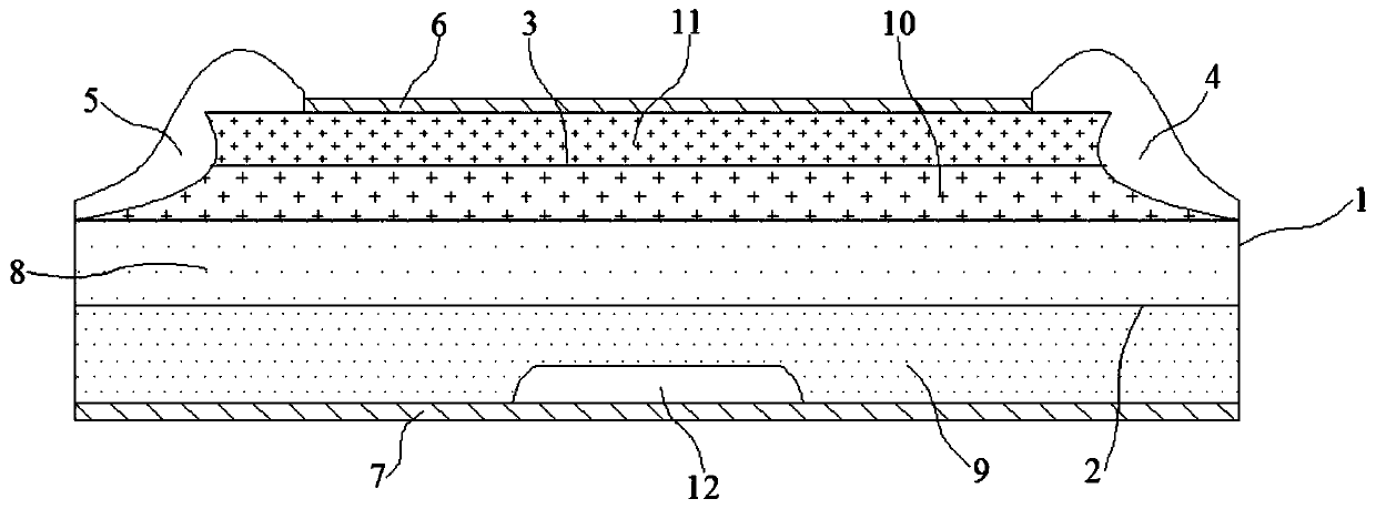
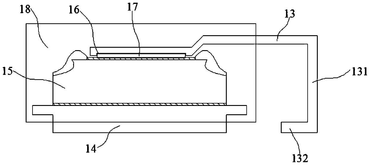
[0035] Embodiment 1~4: a kind of surface mount type TVS device, comprise upper lead frame 13, lower lead frame 14 and chip 15, described upper lead frame 13, lower lead frame 14 welding part and chip are respectively positioned at epoxy insulator 18, the welding portion located at one end of the upper lead frame 13 has a groove 16, and the respective welding portions of the upper lead frame 13 and the lower lead frame 14 are respectively connected to the first metal layer 6 and the second metal layer 7 of the chip 15. The soldering piece 17 is electrically connected between them. The welding piece 17 is embedded in the groove 16 of the upper lead frame 13 and the thickness of the welding piece 17 is greater than the depth of the groove 16. The other end of the upper lead frame 13 is a bending area 131. This bending The end of the bending area 131 is a pin portion 132, and the pin portion 132 of the upper lead frame 13 and the lower part of the lower lead frame 14 are located on...

Embodiment 1

[0045]The release agent in Example 1 is silicone oil, and the flame retardant is a phosphorus-nitrogen series flame retardant; the release agent in Example 2 is an organosilicon polymer, and the flame retardant is a crystal water salt flame retardant; Embodiment The release agent in 3 is fluorine-containing silicone oil, and the flame retardant is crystal water salt flame retardant; the release agent in embodiment 4 is isooctyl ester, and the flame retardant is phosphorus nitrogen series flame retardant and crystal water Mixture of salt flame retardants.

[0046] The raw material preparation method of above-mentioned epoxy insulator 18 comprises the following steps:

[0047] S1. Mix 80-100 parts of epoxy resin and 40-60 parts of phenol resin in a reactor at 70-110 degrees Celsius for hot-melt mixing, stir evenly, and then pulverize into powder after cooling;

[0048] S2. Mix 75-90 parts of silicon micropowder, 5-15 parts of flame retardant and 2-6 parts of γ-aminopropyltrieth...


PUM


Abstract

The invention discloses a surface mounted TVS device, which comprises an upper lead frame, a lower lead frame and a chip, wherein respective welding parts of the upper lead frame and the lower lead frame and the chip are located in an epoxy insulator, the welding part at one end of the upper lead frame is provided with a groove, the welding parts of the upper lead frame and the lower lead frame are electrically connected with a first metal layer and a second metal layer of the chip respectively through welding strips, and the raw materials of the epoxy insulator include the following components in parts by weight: 80-100 parts of epoxy resin, 40-60 parts of phenol resin, 75-90 parts of silicon micropowder, 5-15 parts of a flame retardant, 2-6 parts of gamma-aminopropyl triethoxysilane, 0.3-2 parts of nano silicon dioxide particles, 0.1-1.5 parts of azabicyclo, 2-8 parts of carboxylated acrylonitrile butadiene rubber, 0.3-2 parts of 2-amino-4-fluoro-1- methoxyphenyl, 0.2-1.5 parts of tri-(dimethylaminomethyl)phenol and 3-8 parts of a demoulding agent. The surface mounted TVS device can greatly reduce the bad phenomena such as punching, layering and porosity when being packaged, alsoenhances the overall mechanical properties of epoxy and effectively ensures the stability of the packaging structure.

Description

technical field [0001] The invention belongs to the technical field of TVS devices, in particular to a surface-mounted TVS device. Background technique [0002] The surface mount TVS device is a kind of diode used for circuit protection, the English abbreviation is TVS, so it is also called TVS diode. When working, the TVS diode and the protected device are connected in parallel in the circuit. When there is a peak voltage in the circuit, the TVS diode is reversely broken down and turned on, so that the subsequent devices are not subject to high voltage impact, so as to achieve the purpose of protection. [0003] The packaging of TVS diodes is an important factor affecting its performance, and epoxy resin accounts for more than 95% of the packaging materials because of its good physical and mechanical properties and electrical properties, as well as low cost and good reliability. Viscosity has always been an influence An important factor in the encapsulation performance of ...

Claims


Application Information

Patent Timeline
IPC IPC(8): H01L29/861H01L23/495H01L23/29H01L23/31C08L63/00C08L13/00C08K13/02C08K3/36C08K5/544C08K5/18
CPCC08K2201/011C08K2201/014C08L63/00C08L2205/03H01L23/295H01L23/3107H01L23/49537H01L29/861C08L13/00C08K13/02C08K3/36C08K5/544C08K5/18H01L2224/32245H01L2224/33181H01L2224/73265H01L2924/181H01L2924/00012
Inventor 廖兵沈礼福
Owner 苏州达晶微电子有限公司
Learn More