Ammonia decomposition device, ammonia decomposition system and hydrogen production method

A technology of ammonia decomposition and heat exchange device, which is applied in the field of hydrogen production, can solve the problems of high residual ammonia gas and incomplete decomposition of ammonia gas, and achieve the effects of improving decomposition efficiency, complete decomposition, and improving device compactness

Active Publication Date: 2019-09-06
福大紫金氢能科技股份有限公司
View PDF13 Cites 12 Cited by
  • Summary
  • Abstract
  • Description
  • Claims
  • Application Information

AI Technical Summary

Problems solved by technology

[0004] Therefore, the technical problem to be solved by the present invention is to overcome the defects of incomplete ammonia decomposition and high residual ammonia in gas products in the prior art, so as to provide an ammonia decomposition device and system and an ammonia decomposition method

Method used


Image

  • Ammonia decomposition device, ammonia decomposition system and hydrogen production method
  • Ammonia decomposition device, ammonia decomposition system and hydrogen production method
  • Ammonia decomposition device, ammonia decomposition system and hydrogen production method

Examples


Embodiment 1

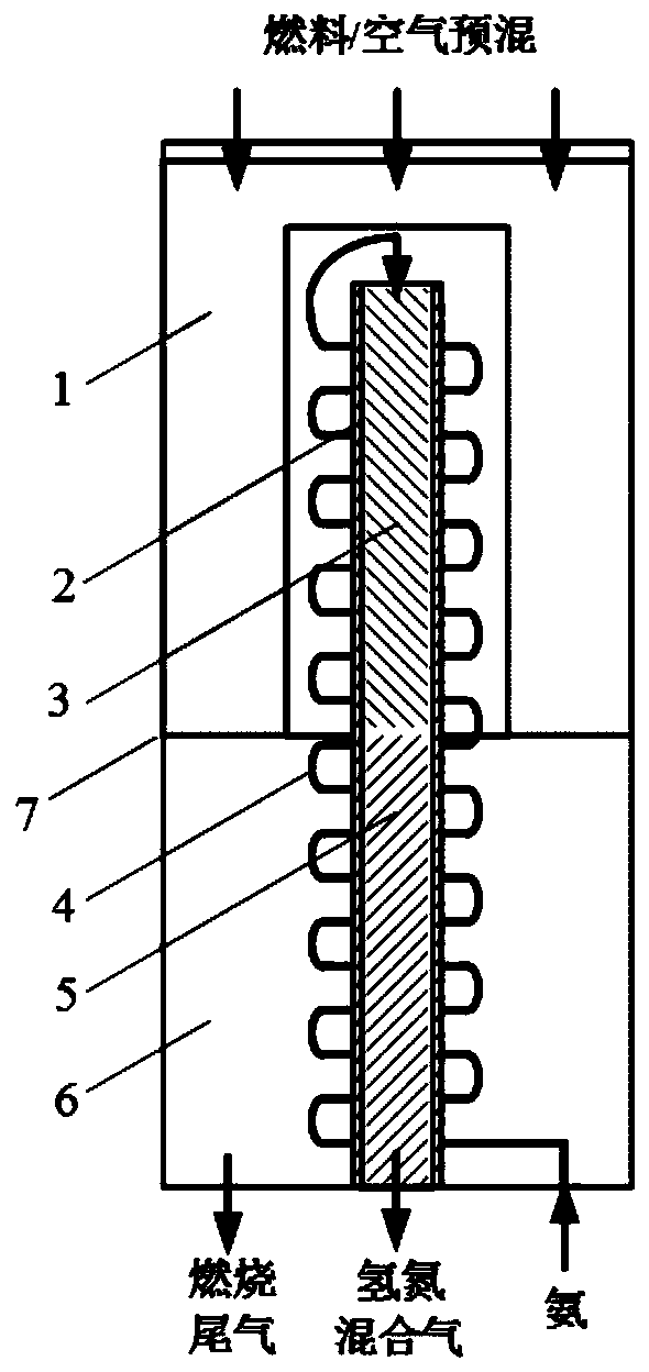
[0047] This embodiment provides an ammonia decomposition device, the structure is shown in figure 1 , including a shell, along the length direction of the shell, the shell includes a heating zone and a heat exchange zone 6 connected in sequence;

[0048] The reaction section 2 includes the first reaction section 3 and the second reaction section 5 which are connected in sequence. The first reaction section is arranged in the heating zone and filled with a nickel-based catalyst to form a nickel-based catalyst layer. The second reaction section is arranged at The heat exchange zone is filled with a ruthenium-based catalyst to form a ruthenium-based catalyst layer; specifically, in this embodiment, the reaction section 2 is a fixed-bed reactor, and the height-to-diameter ratio of the fixed-bed reactor is 8:1. The first reaction section and the second reaction section are arranged in the same fixed bed reactor, the first reaction section 3 is arranged in the fixed bed reactor clos...

Embodiment 2

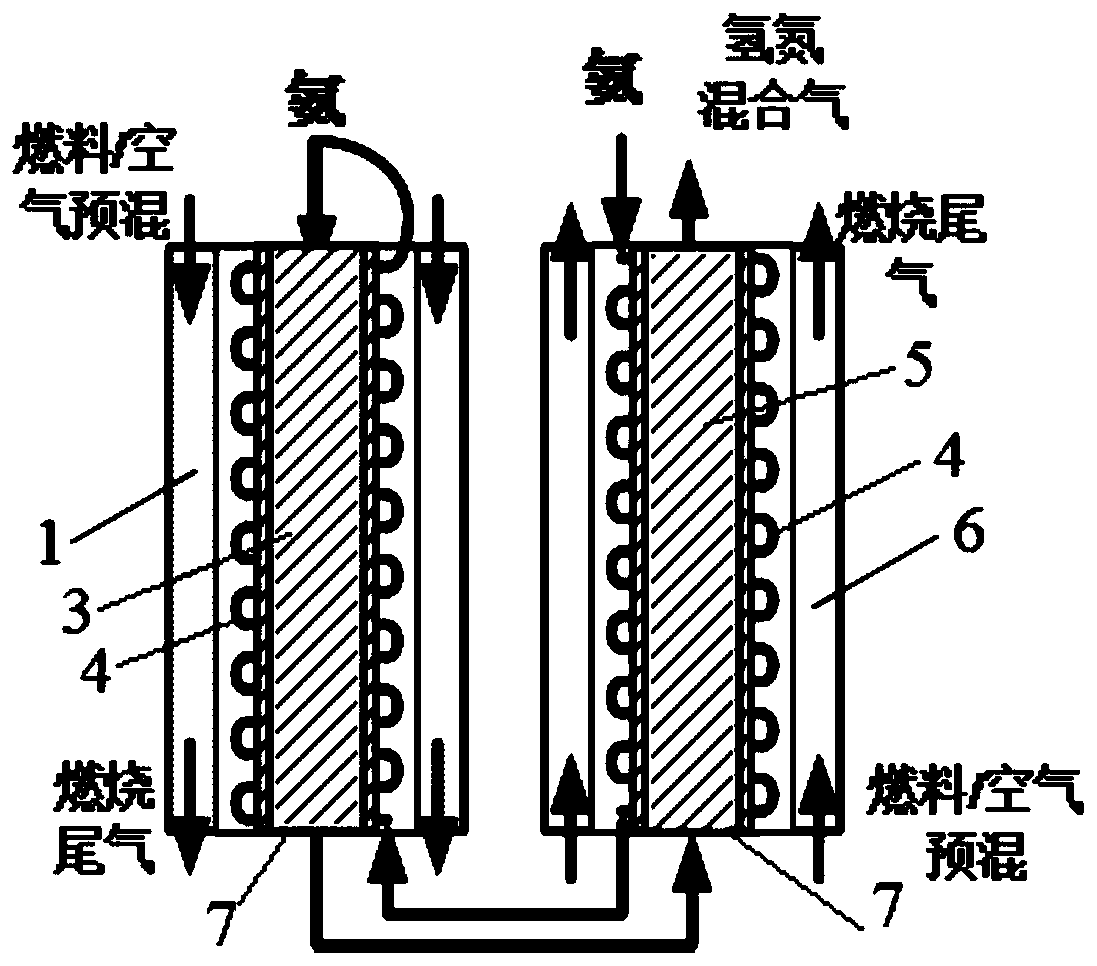
[0059] This embodiment provides an ammonia decomposition device, the structure is shown in image 3 , comprising a shell, and further comprising a sequentially connected heating zone and a heat exchange zone 6, wherein the heating zone and the heat exchange zone are communicated side by side through channels;

[0060] The reaction section includes the first reaction section 3 and the second reaction section 5 which are connected in sequence. The first reaction section is arranged in the heating zone and filled with a nickel-based catalyst to form a nickel-based catalyst layer. The second reaction section is arranged in the heating zone. In the hot zone and filled with a ruthenium-based catalyst to form a ruthenium-based catalyst layer; specifically, in this embodiment, the reaction section is a fixed-bed reactor, and the height-to-diameter ratio of the fixed-bed reactor is 5:1. The first reaction The first section and the second reaction section are respectively arranged in tw...

Embodiment 3

[0071] This embodiment provides an ammonia decomposition device, the structure is shown in figure 1 , including a shell, along the length direction of the shell, the shell includes a heating zone and a heat exchange zone 6 connected in sequence;

[0072] The reaction section 2 includes the first reaction section 3 and the second reaction section 5 which are connected in sequence. The first reaction section is arranged in the heating zone and filled with a nickel-based catalyst to form a nickel-based catalyst layer. The second reaction section is arranged at The heat exchange zone is filled with a ruthenium-based catalyst to form a ruthenium-based catalyst layer; specifically, in this embodiment, the reaction section 2 is a fixed-bed reactor, and the height-to-diameter ratio of the fixed-bed reactor is 8:1. The first reaction section and the second reaction section are arranged in the same fixed bed reactor, the first reaction section 3 is arranged in the fixed bed reactor clos...


PUM


Abstract

The invention belongs to the technical field of hydrogen production, and concretely relates to an ammonia decomposition device, an ammonia decomposition system and a hydrogen production method. The ammonia decomposition device comprises a shell, a heating zone, a heat exchange zone, a reaction section and a heat exchange coil. The heat exchange coil is spirally wound around the outer wall of the reaction section to sufficiently heat ammonia gas, so the heating efficiency of ammonia gas is increased; a first reaction section and a second reaction section which are sequentially communicated arearranged in the reaction section to ensure that the ammonia gas is decomposed after entering the first reaction section in order to generate a nitrogen and hydrogen mixture, so the decomposition efficiency of the ammonia gas is increased; and the second reaction section can perform secondary decomposition on the residual ammonia gas in the nitrogen and hydrogen mixture produced in the first reaction section, so the residual amount of ammonia gas in the nitrogen and hydrogen mixture in the second reaction section is reduced, thereby the ammonia gas is decomposed more thoroughly. The device makes the conversion rate of ammonia gas reach 99.9% or more and the residual amount of ammonia gas in the nitrogen and hydrogen mixture less than 1000 ppm.

Description

technical field [0001] The invention belongs to the technical field of hydrogen production, and in particular relates to an ammonia decomposition device and system and a hydrogen production method. Background technique [0002] A fuel cell is a chemical device that directly converts the chemical energy of fuel into electrical energy, also known as an electrochemical generator. It is the fourth power generation technology after hydropower, thermal power and atomic power. Since the fuel cell converts the Gibbs free energy in the chemical energy of the fuel into electrical energy through an electrochemical reaction, it is not limited by the Carnot cycle effect, so the efficiency is high. In addition, fuel cells and oxygen are used as raw materials, and there are no mechanical transmission parts, no noise pollution, and less harmful gas emissions. It can be seen that from the perspective of saving energy and protecting the ecological environment, fuel cells have good developmen...

Claims


Application Information

Patent Timeline
Patent Type & Authority Applications(China)
IPC IPC(8): C01B3/04C01B3/50C01B3/56
CPCC01B3/047C01B3/503C01B3/56C01B2203/0277C01B2203/1058C01B2203/1064C01B2210/001C01B2210/0014C01B2210/0065Y02E60/36C01B2203/0405C01B2203/043C01B2203/0465C01B2203/066C01B2203/0811C01B2203/0883B01J23/462B01J23/755B01D53/047B01D53/229B01J12/005B01J8/025B01J8/0453B01J8/0496B01J8/0492B01J2219/0009B01D2256/16B01D2257/102B01J2208/00504Y02P20/10B01J8/009B01J8/0285B01J2219/00128B01J2219/00157B01J2219/00907B01J2219/00918C01B2203/042C01B2203/0833C01B2210/0046
Inventor 江莉龙罗宇陈崇启林性贻林建新
Owner 福大紫金氢能科技股份有限公司
Why Eureka
Try Eureka