
High-performance combustion gas turbine gas-exhaust system

A gas turbine and exhaust system technology, applied in mechanical equipment, engine components, climate sustainability, etc., can solve the problems of reducing the efficiency of the gas turbine, overheating the exhaust system shell, large displacement of the exhaust system, etc. The effect of improving safety and prolonging service life

Inactive Publication Date: 2019-10-08
江苏华强新能源科技有限公司
View PDF10 Cites 0 Cited by
  • Summary
  • Abstract
  • Description
  • Claims
  • Application Information

AI Technical Summary

Problems solved by technology

[0003] The exhaust system is an important auxiliary system of a gas turbine, which has a great impact on its efficiency and normal operation. Its main function is to maintain the exhaust pressure to ensure the efficiency of the gas turbine, seal the gas and guide the exhaust direction. If the exhaust system structure design Unreasonable, resonance or failure due to insufficient strength will lead to large displacement of the exhaust system, and the gas turbine gas is not discharged smoothly enough to affect the normal operation of the gas turbine, thereby reducing the efficiency of the gas turbine and even causing the gas turbine to shut down; similarly, if the thermal design is unreasonable, it will Can cause overheating of the exhaust system casing and even gas leakage, which will endanger personal safety and cause the shutdown of the gas turbine

Method used


Image

  • High-performance combustion gas turbine gas-exhaust system
  • High-performance combustion gas turbine gas-exhaust system

Examples


Embodiment 1

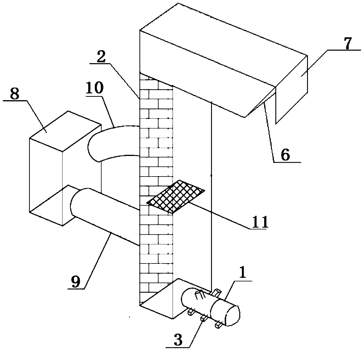
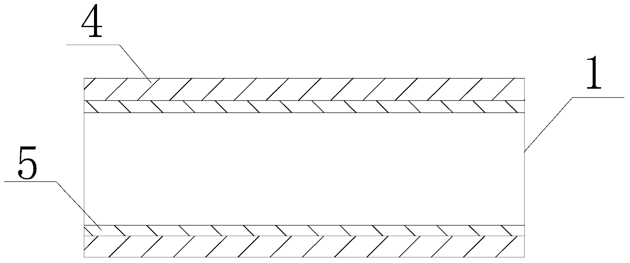
[0041] A high-performance gas turbine exhaust system provided in this embodiment has a structure such as Figure 1-2 As shown, it includes an exhaust tube 1, an exhaust tower 2 and a heat storage device. One end of the exhaust tube 1 is connected to the exhaust port of the gas turbine, and the other end is connected to the exhaust tower 2. The exhaust tower 2 is also connected to a storage heating device;

[0042]The exhaust tube 1 is a cylindrical steel plate structure with one end large and the other end small. There are several bumps 3 on the outer wall of the exhaust tube 1. The inner wall of the exhaust tube 1 is provided with a heat dissipation layer 4. The heat dissipation layer 4 is far away from the bottom of the exhaust tube 1. One side is provided with an isolation layer 5;

[0043] The top of the exhaust tower 2 extends outwards to form an exhaust tower opening 6, and the exhaust tower opening 6 is provided with a rainproof baffle 7 from top to bottom, and the rai...

Embodiment 2

[0050] This embodiment provides that the surfaces of the exhaust pipe 1 and the heat storage tank 8 in Example 1 are respectively provided with a layer of protective layer, and the protective layer is formed by coating the surface of the exhaust pipe and the heat storage tank with a protective coating. The protective coating is formed by mass parts The meter includes the following components:

[0051] Silicone modified epoxy resin: 15 parts, water-based acrylic modified polyurethane emulsion: 30 parts, talcum powder: 7 parts, phosphate: 10 parts, black silicon carbide: 10 parts, fine-grained alumina: 25 parts, dispersant : 5 parts, thickener: 3 parts, leveling agent: 4 parts, adhesion promoter: 3 parts, defoamer: 1 part, silane coupling agent: 5 parts, filler: 7 parts, compound rare earth: 0.01 share;

[0052] The composite rare earth contains the following components by weight percentage: Y: 9%, Sc: 14%, Gd: 16%, Sm: 18%, Pr: 13%, the balance is La, and the sum of the above ...

Embodiment 3

[0061] This embodiment provides that the surfaces of the exhaust pipe 1 and the heat storage tank 8 in Example 1 are respectively provided with a layer of protective layer, and the protective layer is formed by coating the surface of the exhaust pipe and the heat storage tank with a protective coating. The protective coating is formed by mass parts The meter includes the following components:

[0062] Silicone-modified epoxy resin: 17 parts, water-based acrylic modified polyurethane emulsion: 32 parts, talcum powder: 9 parts, phosphate: 18 parts, black silicon carbide: 13 parts, fine-grained alumina: 30 parts, dispersant : 8 parts, thickener: 5 parts, leveling agent: 6 parts, adhesion promoter: 4 parts, defoamer: 3 parts, silane coupling agent: 7 parts, filler: 9 parts, compound rare earth: 0.03 share;

[0063] The composite rare earth contains the following components by weight percentage: Y: 11%, Sc: 17%, Gd: 18%, Sm: 20%, Pr: 15%, the balance is La, and the sum of the abov...


PUM


Abstract

The invention discloses a high-performance combustion gas turbine gas-exhaust system. The high-performance combustion gas turbine gas-exhaust system comprises a gas exhaust barrel, a gas exhaust towerand a heat storage device, wherein one end of the gas exhaust barrel is connected to a gas exhaust hole of a combustion gas turbine, and the other end of the gas exhaust barrel is connected to the gas exhaust tower; the heat storage device is further connected on the gas exhaust tower; the gas exhaust barrel is of a cylindrical steel plate structure with a big end and a small end; a plurality ofbumps are arranged on the outer wall of the gas exhaust barrel; a heat dissipation layer and an isolating layer are arranged on the inner wall of the gas exhaust barrel; the top end of the gas exhausttower is outwards extended to form a gas exhaust tower opening; a plurality of rainproof baffle plates are arranged on the gas exhaust tower opening from top to bottom; and the heat storage device comprises a heat storage box as well as a gas inlet tube and a gas outlet tube which are connected to the heat storage box, an electric louver valve is arranged in the gas exhaust tower, and the position, on the gas exhaust tower, of the electric louver valve is positioned between the gas inlet tube and the gas outlet tube. The high-performance combustion gas turbine gas-exhaust system is simple instructure, is high in safety, can recycle heat energy to certain extent, can reduce energy loss, and improves energy utilization efficiency.

Description

technical field [0001] The invention relates to an exhaust system, in particular to a high-performance gas turbine exhaust system. Background technique [0002] The gas turbine is an internal combustion power machine that uses continuous flowing gas as the working medium to drive the impeller to rotate at high speed, and converts the energy of the fuel into useful work. It is a rotary impeller heat engine. The working process of the gas turbine is that the compressor (that is, the compressor) continuously sucks in air from the atmosphere and compresses it; the compressed air enters the combustion chamber, mixes with the injected fuel and burns to become high-temperature gas, which then flows into the gas turbine Medium expansion works, pushing the turbine impeller to rotate together with the compressor impeller; the working capacity of the heated high-temperature gas is significantly improved, so the gas turbine still has surplus work as the output mechanical work of the gas...

Claims


Application Information

Patent Timeline
Patent Type & Authority Applications(China)
IPC IPC(8): F01D25/30F01D25/00C09D175/14C09D163/00C09D5/08C09D7/61C09D7/65
CPCC08K2003/2227C08K2003/321C08L2201/08C08L2205/035C09D5/08C09D5/18C09D163/00C09D175/14C09D7/61C09D7/65F01D25/005F01D25/30C08L63/00C08L1/14C08L1/286C08K3/34C08K3/32C08K3/22C08K13/02Y02P20/10
Inventor 马永赵俊杰唐敏
Owner 江苏华强新能源科技有限公司
Learn More