Supercharge Your Innovation With Domain-Expert AI Agents!

Fuel cell device, and method for removal of ammonia nitrogen and regeneration of ferric iron

A fuel cell and fuel cell system technology, which is applied in the fields of biotechnology and environmental protection, can solve the problems of loss, increased wastewater treatment cost, substandard effluent color, etc., and achieves the effects of cost saving, low treatment cost and high removal efficiency.

Pending Publication Date: 2019-10-22
CHONGQING INST OF GREEN & INTELLIGENT TECH CHINESE ACADEMY OF SCI
View PDF7 Cites 0 Cited by
  • Summary
  • Abstract
  • Description
  • Claims
  • Application Information

AI Technical Summary

Problems solved by technology

However, due to the relatively high solubility of the Feammox product, ferrous ions, it is easy to lose with the effluent and cause the chroma of the effluent to fail to meet the standard; at the same time, due to the loss of ferrous iron, it is necessary to continuously add iron sources to the system to maintain the progress of Feammox. Increased cost of wastewater treatment

Method used


Image

  • Fuel cell device, and method for removal of ammonia nitrogen and regeneration of ferric iron

Examples


Embodiment 1

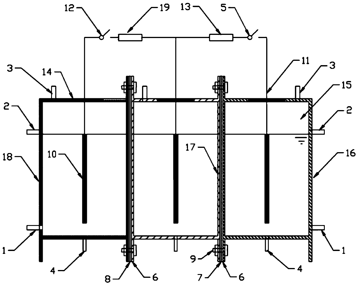
[0028] Such as figure 1 As shown, the purpose of the present invention is to solve the problems of existing anaerobic iron ammonium oxidation technology that the effluent contains high concentration of iron ions and iron regeneration is difficult, and to provide a fuel cell device and a method for ammonia nitrogen removal and ferric iron regeneration.

[0029] A fuel cell device, the main device of which is a three-chamber microbial fuel cell system, which includes three independent reaction areas of anaerobic ammonia oxidation unit, iron redox unit and photobiological reaction unit, which are connected by bolts 9 . The volume ratio of the anammox unit, the iron redox unit and the photobiological reaction unit is 1:1:2. The anammox unit and the iron redox unit are separated by a cation exchange membrane 7 , and the iron redox unit and the photobiological reaction unit are separated by an anion exchange membrane 8 . The anaerobic ammonia oxidation unit, the iron redox unit and...

Embodiment 2

[0043] Such as figure 1 As shown, a fuel cell device, the main device is composed of a three-chamber microbial fuel cell and an external circuit. The anammox unit is made of opaque materials, the iron redox unit is made of light-transmitting materials, and the photobiological reaction unit is made of materials with visible light cut-off infrared light and high transparency. The three units are respectively provided with a water inlet pipe 1, a water outlet pipe 2, an exhaust port 3 and an emptying pipe 4. External circuits are respectively arranged between the anaerobic ammonia oxidation unit and the iron redox unit, between the iron redox unit and the photobiological reaction unit, and resistors and switches are respectively arranged in the external circuits. Carbon-based electrodes 10 are installed in the three reaction units, and the carbon-based electrodes 10 are connected with wires outside the device through titanium wires 11 to form a loop. The anammox unit and the ir...


PUM


Abstract

The invention discloses a fuel cell device, and a method for removal of ammonia nitrogen and regeneration of ferric iron. The fuel cell device comprises a three-chamber microbial fuel cell system andan external circuit, wherein the three-chamber microbial fuel cell system comprises an anaerobic ammonium oxidation unit, an iron redox unit and a photobioreaction unit. In the anaerobic ammoxidationprocess of wastewater, ammonia nitrogen in the anaerobic ammoxidation unit is mainly oxidized into nitrogen. In the iron redox unit, ferric iron receives electrons and is thus reduced into ferrous iron. In the process of iron regeneration, the ferrous iron in the iron redox unit is anaerobically oxidized into ferric iron. Photosynthetic bacteria in the photobioreaction unit utilize electrons on electrode to synthesize single-cell proteins. The method of the invention does not need aeration and an external carbon source, and has high ammonia nitrogen removal efficiency and low treatment cost; effluent obtained after treatment by the method does not contain elemental iron, and elemental iron on a negative electrode is not lost; and compared with a manner of adding an oxidizing agent for oxidation, cost for regeneration of ferric iron is reduced.

Description

technical field [0001] The invention relates to an anaerobic iron ammonium oxidation device for wastewater denitrification, in particular to a fuel cell device and a method for removing ammonia nitrogen and regenerating ferric iron, belonging to the fields of biotechnology and environmental protection. Background technique [0002] The traditional water treatment process realizes the denitrification of wastewater through the nitrification-denitrification process. Anammox reaction means that under anaerobic or anoxic conditions, anammox microorganisms convert NO 2 - N, sulfate, iron and manganese ions or humic acid are electron acceptors, oxidizing NH 4 + -N is nitrogen for biological processes. Compared with the traditional wastewater nitrification-denitrification process, ANAMMOX does not require a large amount of aeration, nor does it require additional carbon sources, which can reduce 50% of aeration, 100% of organic carbon sources and 90% of operating costs , and th...

Claims


Application Information

Patent Timeline
IPC IPC(8): C02F3/34C02F3/00H01M8/16C02F101/16
CPCC02F3/34C02F3/005H01M8/16C02F2101/16Y02E60/50
Inventor 王兴祖刘鸿宋诚
Owner CHONGQING INST OF GREEN & INTELLIGENT TECH CHINESE ACADEMY OF SCI
Features
  • R&D
  • Intellectual Property
  • Life Sciences
  • Materials
  • Tech Scout
  • Unparalleled Data Quality
  • Higher Quality Content
  • 60% Fewer Hallucinations
Learn More