
Triaxial hard cable component

A cable assembly, triaxial technology, applied in the field of triaxial rigid cable assembly, can solve the problems of cable electrical performance failure, melting of inner insulation layer, heat can not be concentrated, etc., to achieve fast and reliable connection, prevent oxidation, increase creepage effect of distance

Active Publication Date: 2019-10-25
CHINA AVIATION OPTICAL-ELECTRICAL TECH CO LTD
View PDF7 Cites 2 Cited by
  • Summary
  • Abstract
  • Description
  • Claims
  • Application Information

AI Technical Summary

Problems solved by technology

[0003] 1) The termination of the shielding layer of the triaxial hard cable is generally welded. Since the product needs to withstand a high temperature of 226°C, it needs to be welded with high-temperature solder wire. Due to the large welding area, the required welding time is longer, and the inner insulation of the cable The maximum temperature resistance of the material is 190°C, which causes the inner insulating layer to melt when the inner shielding layer of the cable is welded to the intermediate conductor of the connector;
[0004] 2) The outer shielding layer of the cable is a copper tube, which produces mirror reflection during laser welding, and the heat cannot be concentrated, and the welding of the copper and the stainless steel shell of the connector is made of different materials, and the welding strength is low
[0005] 3) The inner shielding layer and the outer shielding layer of the feedthrough line are copper tubes, which are thicker and have better ductility. It is extremely difficult to strip the wires by using the traditional stripping process, and it is easy to cause the cable shielding layers to overlap each other, making the cable electric performance failure

Method used


Image

  • Triaxial hard cable component
  • Triaxial hard cable component
  • Triaxial hard cable component

Examples


Embodiment Construction

[0031] In order to further illustrate the technical means and technical effects adopted by the present invention, the present invention will be described in detail below in conjunction with specific embodiments.

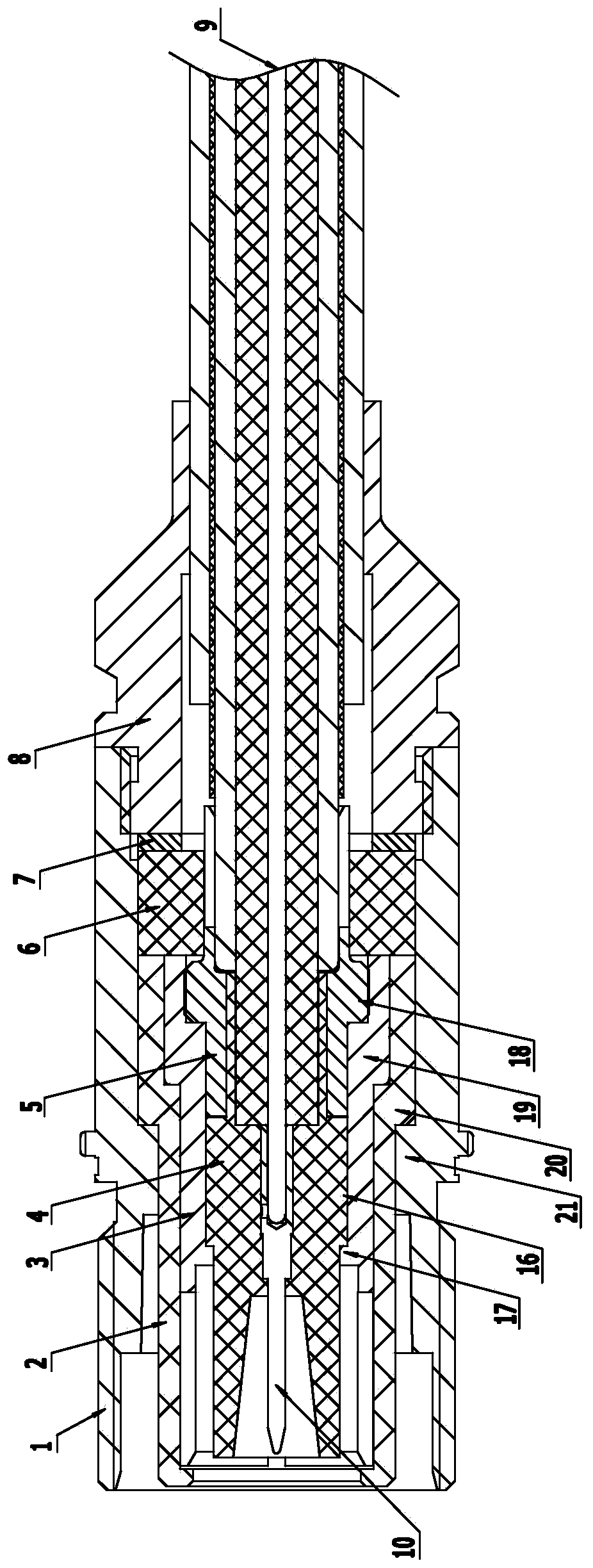
[0032] For the sake of illustration, define Figure 1-Figure 3 The left end is the front end (head), and the right end is the rear end (tail), but the terms indicating orientation such as "front" and "rear" in the present invention are only based on the orientation or positional relationship shown in the figure, and are only for convenience The present invention is described and should not be construed as limiting the present invention.

[0033] like figure 1 As shown, the triaxial hard cable assembly of the present invention includes an outer shell 1, an outer insulator 2 assembled in the outer shell, an intermediate conductor 3 assembled in the outer insulator, an inner insulator 4 assembled in the intermediate conductor, and an inner bushing 5 , the insulating p...


PUM


Abstract

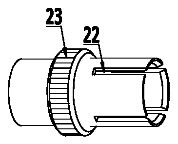
The invention relates to a triaxial hard cable component. A triaxial hard cable is assembled in a shell at the tail part of a connector, penetrates an inner bushing and an inner insulator in the connector and is welded with a central contact element by adopting a high-temperature soldering tin wire; the periphery of the inner bushing is provided with knurls and is fixed in a middle conductor in aforced mounting mode, the tail end of the inner bushing is provided with an opening to enable the tail end of the inner bushing to be an elastic structure, the cable inner shielding layer is insertedinto the tail end of the elastic structure of the inner bushing to have a fixing effect on the inner shielding layer, the outer shielding layer of the triaxial hard cable is connected with the tail end of the tail shell in an induction brazing mode, and the connection of the periphery of the inner shielding layer and the tail end of the inner bushing is plated with gold; and the connection of theinner wall of the tail portion of the shell and the outer shielding layer is plated with nickel. The triaxial hard cable component can achieve quick and reliable connection of the triaxial hard cableand the connector, is reliable in connection, ensures the reliability and the sealing property of the connection, improves the welding strength and ensures the reliable sealing performance and the good electrical performance of the component under various working conditions.

Description

technical field [0001] The invention relates to a triax rigid cable assembly. Background technique [0002] The feedthrough feedthrough for nuclear testing equipment outside the nuclear power plant is a triaxial rigid cable, the central conductor, inner shield, and outer shield are made of copper, the inner insulation is polysulfone, and the outer insulation is polyimide. After the feedthrough of the feedthrough is integrated with the connector, it needs to meet the working environment requirements such as 60-year design life, high temperature resistance, high radiation resistance, earthquake resistance, design basis accident (high temperature, high pressure steam environment), etc. Currently, the integration of feedthroughs and connectors has the following difficulties: [0003] 1) The termination of the shielding layer of the three-axis hard cable is generally welded. Since the product needs to withstand high temperature of 226 ° C, it needs to be welded with high-tempera...

Claims


Application Information

Patent Timeline
Patent Type & Authority Applications(China)
IPC IPC(8): H01B11/18H01B11/20H01B7/17H01B7/02H01B7/00
CPCH01B7/00H01B7/0216H01B7/17H01B11/18H01B11/1895H01B11/206
Inventor 薛欢欢江浪陈继利郭俊磊朱彧
Owner CHINA AVIATION OPTICAL-ELECTRICAL TECH CO LTD
Learn More