A kind of ammonia combustion control method and ammonia combustion device
A control method and ammonia combustion technology, applied in the field of ammonia combustion control and ammonia combustion devices, can solve the problems of complex structure of the device, unfavorable promotion and application of ammonia combustion technology, high cost, etc., and achieve simple structure of the device and low pressure resistance requirements , the effect of easy operation
- Summary
- Abstract
- Description
- Claims
- Application Information
AI Technical Summary
Problems solved by technology
Method used
Image
Examples
Embodiment 1
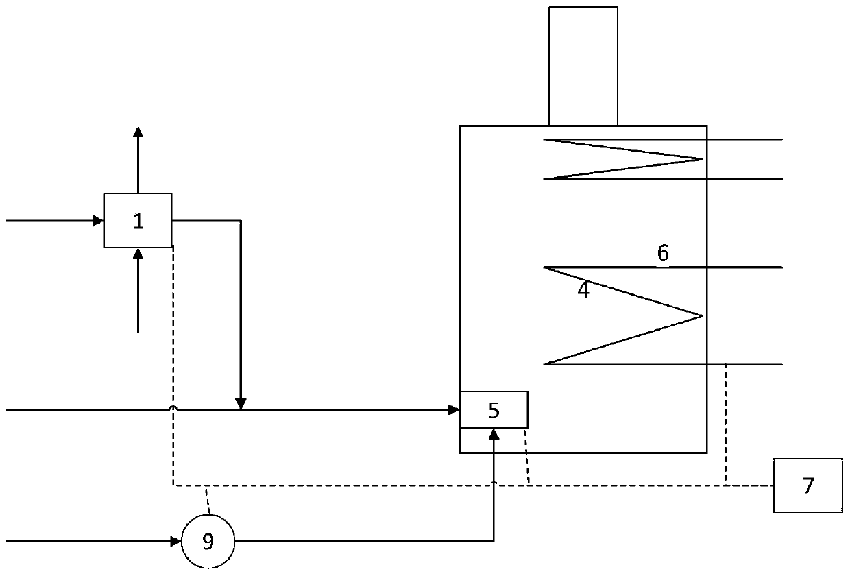
[0065] combine figure 1 The illustrated ammonia combustion device is used to illustrate this embodiment, and the ammonia combustion device is provided with an evaporation box 1 , a combustion chamber 4 , a burner 5 , a heat exchange coil 6 and a controller 7 .
[0066] Under the real-time control of the controller 7, the liquid ammonia is completely vaporized in the evaporation box 1. While providing cooling capacity to the outside, the obtained gaseous ammonia is passed into the burner 5 together with the carbon-containing combustible gas, and after being mixed with air Burn stably in the combustion chamber 4, and provide heat to the outside through the heat exchange coil 6;
[0067] The standard state volume flow ratio of gaseous ammonia, carbon-containing combustible gas and air fed into the burner 5 is 1:b:c, wherein, b>0.3, c=(3.57+b×d)×(0.85~1.2 ), d is the stoichiometric air-fuel ratio of the carbon-containing combustible gas. For example, select propane as the carbon...
Embodiment 2
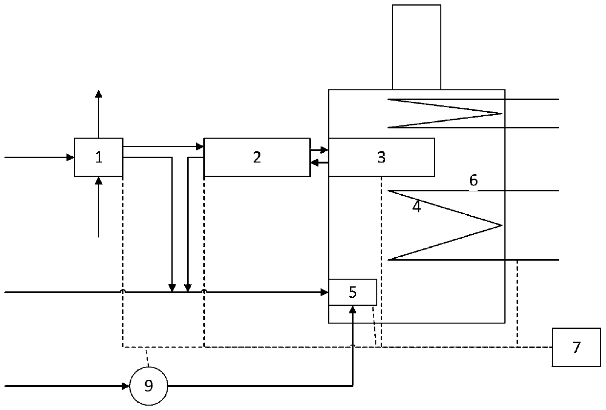
[0072] combine figure 2 The ammonia combustion device shown is an illustration of this embodiment. The ammonia combustion device is provided with an evaporation tank 1 , a heat exchanger 2 , a thermal cracker 3 , a combustion chamber 4 , a burner 5 , a heat exchange coil 6 and a controller 7 .
[0073] In this embodiment, the thermal cracker 3 is filled with a nickel catalyst (Southwest Institute Z204), and the working temperature is 1000K-1100K; the thermal cracker 3 is placed in the area of the combustion chamber 4 where the high-temperature flue gas temperature is 1050K-1150K Inside;
[0074] In this embodiment, under the real-time control of the controller 7, the liquid ammonia is completely vaporized in the evaporation box 1. While providing cooling capacity to the outside, the obtained residual gaseous ammonia, hydrogen and nitrogen generated by the cracking of part of the gaseous ammonia The mixture and combustible gas containing carbon are passed into the burner 5 ...
Embodiment 3
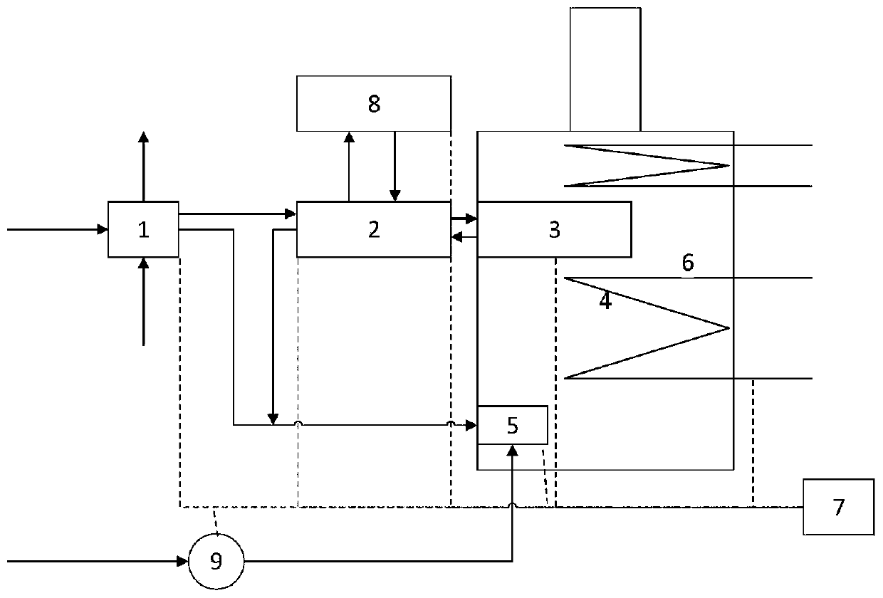
[0080] combine image 3 The shown ammonia combustion device illustrates this embodiment, and the shown ammonia combustion device is provided with an evaporation box 1, a heat exchanger 2, a thermal cracker 3, a combustion chamber 4, a burner 5, a heat exchange coil 6, a controller 7 and Auxiliary ammonia thermal cracker 8.
[0081] In this embodiment, carbon-containing combustible gas is not configured.
[0082] In this embodiment, the thermal cracker 3 is filled with an iron catalyst (A106 type), and the working temperature is 800K to 950K; the thermal cracker 3 is placed in the combustion chamber 4 where the high temperature flue gas temperature is 850K to 1000K ;
[0083] In this embodiment, under the real-time control of the controller 7, the liquid ammonia is completely vaporized in the evaporation box 1. While providing cooling capacity to the outside, the obtained residual gaseous ammonia, hydrogen and nitrogen generated by the cracking of part of the gaseous ammonia ...
PUM
 Abstract
Description
Claims
Application Information
 - R&D
- Intellectual Property
- Life Sciences
- Materials
- Tech Scout
- Unparalleled Data Quality
- Higher Quality Content
- 60% Fewer Hallucinations
Browse by: Latest US Patents, China's latest patents, Technical Efficacy Thesaurus, Application Domain, Technology Topic, Popular Technical Reports.
© 2025 PatSnap. All rights reserved.Legal|Privacy policy|Modern Slavery Act Transparency Statement|Sitemap|About US| Contact US: help@patsnap.com


