Carbon fiber composite material infrared laser surface treatment process

An infrared laser and surface treatment technology, used in laser welding equipment, manufacturing tools, metal processing equipment, etc., can solve the problems of insufficient comprehensive mechanical properties of composite materials, damage to substrates, high plant and environmental requirements, etc. Excellent controllability and stability, reduced manufacturing costs, and reduced maintenance time

Inactive Publication Date: 2019-12-13
CIVIL AVIATION FLIGHT UNIV OF CHINA
View PDF5 Cites 9 Cited by
  • Summary
  • Abstract
  • Description
  • Claims
  • Application Information

AI Technical Summary

Problems solved by technology

For example, traditional surface grinding or sandblasting is time-consuming, inefficient, and inaccurately controls the depth of surface removal, which may expose surface fibers and cause unstable surface quality; corona discharge and plasma treatment can remove surface pollutants, Roughen the surface and introduce oxygen-containing functional groups, but have high requirements on the plant and the environment, which limits the size of the carbon fiber composite components to be treated; chemical cleaning methods use strong acids, strong alkalis or various amine solvents, which are harmful to the environment and operators. There is greater damage, and it is easy to cause damage to the substrate
The electrochemical oxidation method is actually applied in the industry, because the electrochemical oxidation method has mild reaction, easy control of the reaction degree, and remarkable treatment effect; however, the electrochemical oxidation method has large energy consumption, large amount of waste liquid, and great impact Environmental pollution is a big problem, and the comprehensive mechanical properties of composite materials have not been fully utilized

Method used

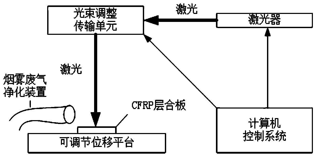
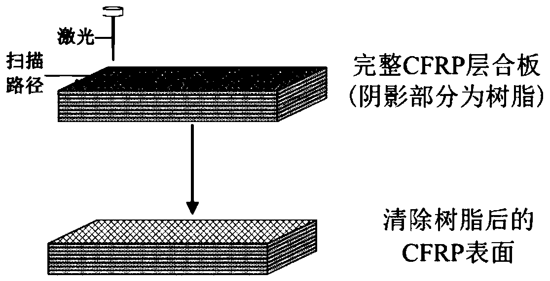
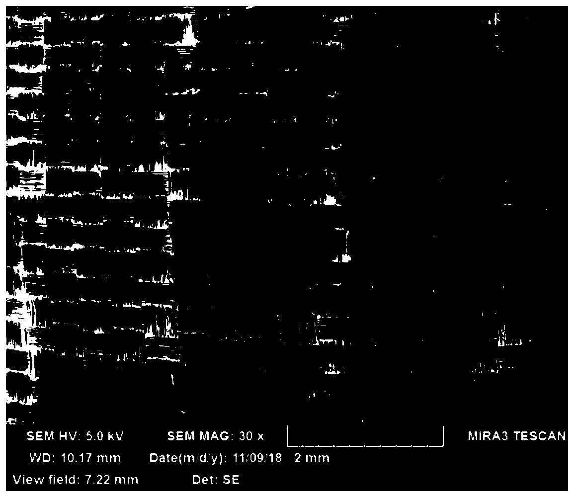

Image

  • Carbon fiber composite material infrared laser surface treatment process
  • Carbon fiber composite material infrared laser surface treatment process
  • Carbon fiber composite material infrared laser surface treatment process

Examples


Embodiment 1-3

[0092] An infrared laser surface treatment process for carbon fiber composite materials, using an energy density of 1.07J / cm 2 , 1.25J / cm 2 and 1.43J / cm 2 Infrared laser for surface treatment of carbon fiber composite materials;

[0093] In Examples 1-3, the power of the laser is 12W, 14W and 16W respectively, the frequency of the laser is 100kHz, the spot diameter is 119μm, the wavelength of the laser is 1064nm, the pulse width of the laser is 200ns, and the scanning speed of the laser is 800mm / s , the scanning times of the laser is 5 times, and the defocusing amount of the laser is 4mm.

Embodiment 4-5

[0095] A carbon fiber composite material infrared laser surface treatment process, different from Example 2, the energy density is 1.25J / cm 2 The scanning speeds of the laser are 700mm / s and 900mm / s respectively, and the scanning times are 5 times.

Embodiment 6-7

[0097] An infrared laser surface treatment process for carbon fiber composite materials is different from Example 2 in that the number of laser scans is 3 and 7 respectively.


PUM

PropertyMeasurementUnit
wavelengthaaaaaaaaaa

Abstract

The invention relates to the field of composite material processing and treatment, and particularly provides a carbon fiber composite material infrared laser surface treatment process. According to the surface treatment process, an infrared laser with the energy density of 0.9-1.5 J / cm<2> is adopted for the surface treatment of the carbon fiber composite material; the high-energy pulse of a laseris utilized to make the complex physical and chemical reactions such as instant evaporation, peeling or cracking conduct on dirt or resin on the surface of the composite material, and the purpose of cleaning the surface of the composite material efficiently is achieved. The laser with the specific energy density is adopted for surface treatment of the carbon fiber composite, the resin or dirt on the surface of the composite material can be completely removed, residual resin or dirt is avoided on the surface, it can be guaranteed that the carbon fiber is not damaged, and thus the mechanical property of the composite material can be guaranteed.

Description

technical field [0001] The invention relates to the field of composite material processing, in particular to an infrared laser surface treatment process for carbon fiber composite materials. Background technique [0002] Carbon fiber reinforced resin-based composites (also known as carbon fiber composites, CFRP, Carbon Fiber Reinforced Polymer / Plastic) refer to resin-based composites reinforced with carbon fibers and their products. Compared with traditional metal materials, carbon fiber-reinforced resin-based composites have A series of excellent properties such as high specific strength, high specific modulus, high temperature resistance, corrosion resistance, fatigue resistance, creep resistance, easy conductivity, easy heat transfer and small thermal expansion coefficient, are used in aviation, aerospace, automobile industry, sporting goods , construction, civil engineering, construction and transportation and other fields, so in terms of military and civilian uses, the ...

Claims


Application Information

Patent Timeline
Patent Type & Authority Applications(China)
IPC IPC(8): B23K26/352B23K26/0622B23K26/082B23K26/70B08B3/12B23K103/16
CPCB08B3/12B23K26/0622B23K26/082B23K26/352B23K26/702B23K2103/16B23K2103/38
Inventor 钟勉杨文锋徐艺张殊伦刘畅
Owner CIVIL AVIATION FLIGHT UNIV OF CHINA
Why Eureka
Try Eureka