Integrated diffusion layer of fuel cell and preparation method thereof, and application of integrated diffusion layer of fuel cell

A fuel cell and gas diffusion layer technology, applied in the field of fuel cell gas diffusion layer, can solve the problem of low conductivity of asphalt-based CFs, achieve the effects of reducing raw materials and preparation costs, facilitating material distribution, and strong mass transfer capacity

Active Publication Date: 2019-12-20
DALIAN JIAOTONG UNIVERSITY
View PDF4 Cites 1 Cited by
  • Summary
  • Abstract
  • Description
  • Claims
  • Application Information

AI Technical Summary

Problems solved by technology

However, the relatively low conductivity of pitch-based CFs limits its wide application. In recent years, researchers have proposed several methods to improve the conductivity of pitch-based CFs by adding various nanofillers, adding nanoporous carbon materials to composite materials. , not only improve the porosity of the material, but also have a positive impact on the physical and chemical properties of CFs due to the porosity of the carbon material itself and the network structure formed between two or more materials [9]

Method used


Image

  • Integrated diffusion layer of fuel cell and preparation method thereof, and application of integrated diffusion layer of fuel cell
  • Integrated diffusion layer of fuel cell and preparation method thereof, and application of integrated diffusion layer of fuel cell
  • Integrated diffusion layer of fuel cell and preparation method thereof, and application of integrated diffusion layer of fuel cell

Examples


Embodiment 1

[0035] Example 1 Preparation of integrated diffusion layer

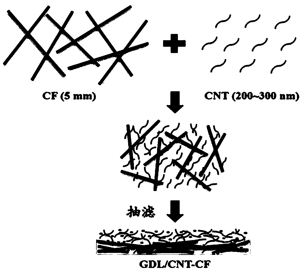
[0036] Weigh 45 mg of multi-walled carbon nanotubes in a 100 mL tall beaker, add 45 mL of nitrogen-methylpyrrolidone (NMP) as a dispersant (about 1 mg mL -1 ), sonicate for 1h, disperse with a high-speed disperser at a speed of 20000rmp for 3min, as solution A; weigh 15mg of carbon fiber, add 45ml of NMP (1 / 3mg mL -1 ), ultrasonication for 30min, as solution B; pour A into solution B, then add 6mg PTFE slurry (10%), sonicate in an ultrasonic cleaner for 1h, then stir at a high speed of 20000rpm for 3min, then use the prepared suction filter The device quickly filters into a membrane, and the filter membrane is a PTFE membrane (45 μm). Then vacuum-dried at 130°C, and finally placed the preformed diffusion layer in a high-temperature tube furnace at 350°C for 3 hours to obtain a new integrated diffusion layer (GDL / CNT-CF). The schematic diagram of the preparation method is as figure 1Shown; The solid photo of the pr...

Embodiment 2

[0038] Preparation of GDL / Toray-060H: Use commercial Toray-060H carbon paper as the substrate of the anode and cathode diffusion layers, take appropriate amount of polytetrafluoroethylene (PTFE) and carbon powder (XC-72), stir evenly to form a mixed slurry, and then apply The microporous layer is prepared by coating on the base layer by coating method. The loadings of XC-72R and PTFE in the anode / cathode microporous layers were 2 mg cm -2 , 10wt% and 2mgcm -2 , 40wt%.

Embodiment 3

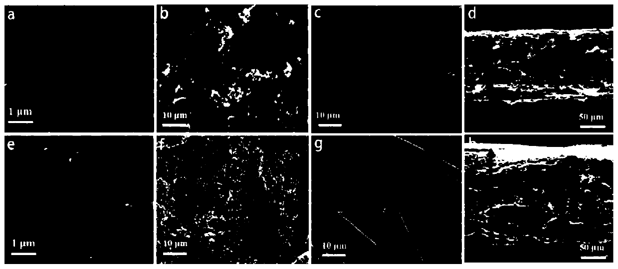
[0040] Adopt the JSM-6360LV type field emission scanning electron microscope (SEM) of JOEL company to characterize the structure and microscopic appearance of the diffusion layer prepared in embodiment 1, and compare with the commercial diffusion layer in embodiment 2, the comparison results are as follows image 3 shown.

[0041] It can be seen from the microscopic appearance of the front side that the carbon nanotubes are dispersed very uniformly, and the PTFE balls are evenly embedded on the carbon nanotubes; from the topography of the back side, it can be seen that the carbon fibers and carbon nanotubes are intertwined with each other. Some larger pores are formed between carbon fibers; from the cross-sectional comparison diagram, the thickness of the new GDL is only 120nm, which is about 1 / 2 of the commercial diffusion layer. A large number of carbon nanotubes can directly act as a microporous layer and contact the catalytic layer, while the bottom has more carbon fibers,...


PUM

PropertyMeasurementUnit
lengthaaaaaaaaaa
thicknessaaaaaaaaaa
thicknessaaaaaaaaaa

Abstract

The invention relates to a gas diffusion layer of a fuel cell, in particular to an integrated diffusion layer and a preparation method thereof and application of an integrated diffusion layer. According to the preparation method, the novel integrated diffusion layer is prepared by taking carbon fibers as a skeleton, compounding multi-walled carbon nanotubes, taking nitrogen methyl pyrrolidone as adispersing agent for dispersing at a high speed and taking polytetrafluoroethylene (PTFE) as a binder and a water repellent through a reduced pressure suction filtration forming method in one step. The integrated diffusion layer replaces a traditional diffusion layer composed of carbon paper and a micropore layer, and when the integrated diffusion layer is applied to a cathode of a direct methanol fuel cell or serves as an anode diffusion layer and a cathode diffusion layer at the same time, the maximum power density of a single cell is improved by 20% and 35% compared with a commodity diffusion layer. The integrated diffusion layer is applied to a zinc-air battery oxygen electrode, the maximum power density reaches up to 200mA cm-2, and a potential direction is provided for exploration of a high-performance and low-cost novel diffusion layer process and material of a fuel cell.

Description

technical field [0001] The invention relates to a fuel cell gas diffusion layer, in particular to an integrated diffusion layer and its preparation method and application. Background technique [0002] Proton exchange membrane fuel cells (PEMFC), direct methanol fuel cells (DMFC) and metal-air batteries have become popular in recent years because of their high power density, high energy conversion efficiency, low-temperature start-up, no pollution, and light weight. Research Hotspots [1-3] . Membrane electrode (MEA), the core component in fuel cells, is usually prepared by hot pressing process from gas diffusion layer, catalytic layer and proton exchange membrane. The gas diffusion layer is located between the catalytic layer and the flow field plate, and generally consists of two parts: the backing layer (BackingLayer, BL) and the microporous layer (Microporous Layer, MPL). [4] . The support layer mainly supports the microporous layer and the catalytic layer, collects c...

Claims


Application Information

Patent Timeline
Patent Type & Authority Applications(China)
IPC IPC(8): H01M4/86H01M4/88H01M8/10H01M8/1011H01M12/06
CPCH01M4/8807H01M4/8605H01M8/10H01M8/1011H01M12/06Y02E60/50
Inventor 赵红舒清柱王素力魏伟
Owner DALIAN JIAOTONG UNIVERSITY
Why Eureka
Try Eureka