Lithium metal electrode prepared through 3D printing technology and preparation method thereof

A lithium metal electrode, 3D printing technology, applied in the direction of electrode manufacturing, negative electrode, battery electrode, etc., can solve the problems that lithium-ion batteries are difficult to meet the application, and achieve excellent deep charge and deep discharge performance, high Coulombic efficiency, good rate performance Effect

Active Publication Date: 2019-12-31
BEIHANG UNIV
View PDF19 Cites 10 Cited by
  • Summary
  • Abstract
  • Description
  • Claims
  • Application Information

AI Technical Summary

Problems solved by technology

In recent years, with the rapid development of mobile devices, vehicle electrification, grid storage, 5G information transmission technology, biochips and wearable electronic devices, the

Method used


Image

  • Lithium metal electrode prepared through 3D printing technology and preparation method thereof
  • Lithium metal electrode prepared through 3D printing technology and preparation method thereof
  • Lithium metal electrode prepared through 3D printing technology and preparation method thereof

Examples


Embodiment 1

[0049] This embodiment provides a kind of printing paste, and its composition is made of titanium carbide (Ti carbide) in the transition metal carbide 3 C 2 T x ) and water, where Ti 3 C 2 T x The preparation process includes steps 1) to 3):

[0050] Step 1): Put 2g Ti 3 AlC 2 Add the powder into a mixture of 4g lithium fluoride (LiF) and 40mL 12mol / mL hydrochloric acid (HCl), and stir for 40h in a water bath at 30°C;

[0051] Step 2): The suspension obtained in step 1) was suction filtered, washed repeatedly with deionized water, and ultrasonically treated for 30 minutes to obtain Ti 3 C 2 T x A suspension in which nanosheets are uniformly dispersed;

[0052] Step 3): The suspension obtained in step 2) was further concentrated to obtain a 300 mg / ml slurry, which was the printing paste of the present invention.

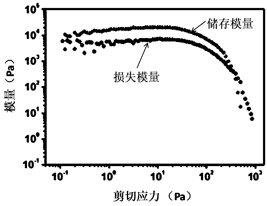
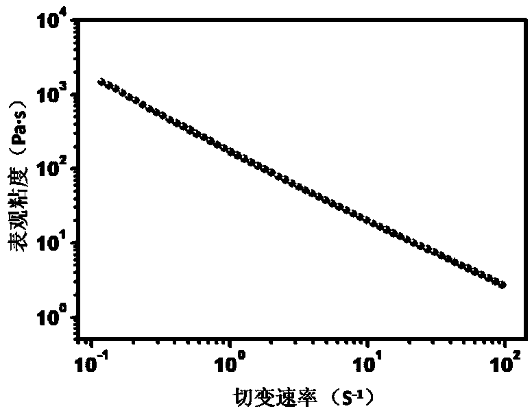
[0053] The rheological properties of the printing paste are measured by a DHR-2 rotational rheometer (TA Instruments, USA), and the fixture is a 20mm steel...

Embodiment 2

[0056] This embodiment provides a printing paste whose components are composed of graphene and water.

[0057] The preparation steps include: concentrating the graphene solution prepared by the liquid phase exfoliation method (available from the market) through a rotary evaporator to obtain a high-concentration viscous slurry with a concentration of 80 mg / ml, which is the printing slurry of the present invention.

[0058] Measured by a rotational rheometer at a shear rate of 1 s -1 The apparent viscosity of the printing paste was 300 Pa·s.

[0059] Graphene is a two-dimensional conductive material with a sheet structure.

Embodiment 3

[0061] This embodiment provides a printing paste whose components are composed of fluorinated graphite and water. The preparation steps include: dispersing the fluorinated graphite powder in water to prepare a uniform and stable viscous slurry with a concentration of 100 mg / ml.

[0062] measured by a rotational rheometer at a shear rate of 1 s -1 The apparent viscosity of the printing paste was 200 Pa·s.


PUM

PropertyMeasurementUnit
Widthaaaaaaaaaa
Widthaaaaaaaaaa
Surface capacityaaaaaaaaaa

Abstract

The invention discloses a lithium metal electrode prepared through the 3D printing technology and a preparation method thereof. The lithium metal electrode comprises a printing skeleton, wherein the printing skeleton is of a network structure with regular patterns and comprises a grid structure, an array structure, a honeycomb structure, a concentric circle structure or a spiral structure; and lithium metal, which is deposited on the surface of the printing framework and/or is filled in gaps of the printing skeleton. The invention further discloses printing slurry suitable for the method for preparing the lithium metal electrode through the 3D printing technology. According to the method for preparing the lithium metal electrode through the 3D printing technology, by applying the 3D printing technology to preparation of the lithium metal battery, the problem of preparation of microstructure materials which are difficult to industrially manufacture is solved, and the prepared lithium metal electrode shows excellent cycle performance, good rate capability, excellent deep charging and deep discharging performance and high coulombic efficiency; and after multiple times of charging anddischarging, the surface is smooth, and no obvious dendritic crystal is formed.

Description

technical field [0001] The invention relates to the field of secondary batteries, in particular to a lithium metal electrode prepared by 3D printing technology and a preparation method thereof. Background technique [0002] Metal lithium has the highest specific capacity (3860mAh / g) and the lowest electrochemical potential (-3.04V), and is considered to be one of the most potential negative electrode materials. As early as the 1970s and 1980s, metal lithium batteries began to In 1972, Exxon Petroleum Company developed Li / TiS 2 Lithium secondary batteries, followed by Li / MnO 2 , Li / Ag 2 V 4 o 11 Lithium metal batteries have been researched and developed one after another, but metal lithium is used as the negative electrode material. In the process of repeated charge and discharge, metal lithium deposits unevenly at the interface to form dendrites. With the growth of dendrites, it is possible to pierce the separator and cause a short circuit in the battery. lead to securi...

Claims


Application Information

Patent Timeline
IPC IPC(8): H01M4/134H01M4/1395H01M4/04H01M4/38H01M4/62H01M4/66H01M4/74H01M4/78B33Y10/00B33Y80/00
CPCB33Y10/00B33Y80/00H01M4/0402H01M4/0411H01M4/134H01M4/1395H01M4/382H01M4/628H01M4/66H01M4/663H01M4/745H01M4/78H01M2004/027Y02E60/10
Inventor 杨树斌沈锴
Owner BEIHANG UNIV
Why Eureka
Try Eureka