Electric spark and electrolytic continuous machining method and tool for efficient plane milling

A processing method and electric spark technology, applied in the field of EDM, can solve the problems of time consumption, reduce processing efficiency, and cannot be reused, and achieve the effects of easy disassembly and replacement, reduced loss, and improved processing efficiency.

Active Publication Date: 2020-02-07
NANJING UNIV OF AERONAUTICS & ASTRONAUTICS
View PDF6 Cites 4 Cited by
  • Summary
  • Abstract
  • Description
  • Claims
  • Application Information

AI Technical Summary

Problems solved by technology

In the time difference, the surface processed by EDM may form an oxide layer again, which will hinder the efficient operation of subsequent electrolytic machining
In addition, after EDM, no matter other tools or equipment are used for electrolytic machining, operations such as tool setting must be performed first, which will consume a certain amount of time and reduce processing efficiency
For EDM-electrolysis composite machining, the current research is mainly on the removal of materials by EDM, supplemented by the removal of the recast layer of EDM through electrolysis. Most of the solutions used are ultra-low concentration salt solutions, which cannot be achieved through High-efficiency electrolysis; some scholars try to use the low-concentration solution required for electric spark discharge and the high-concentration solution required for electrolysis to realize composite electrolytic processing at the same time during processing, but after this method is processed, two solutions with different concentrations are mixed in the Together, it cannot be reused, which is not conducive to long-term mass industrial production

Method used


Image

  • Electric spark and electrolytic continuous machining method and tool for efficient plane milling
  • Electric spark and electrolytic continuous machining method and tool for efficient plane milling
  • Electric spark and electrolytic continuous machining method and tool for efficient plane milling

Examples


Embodiment Construction

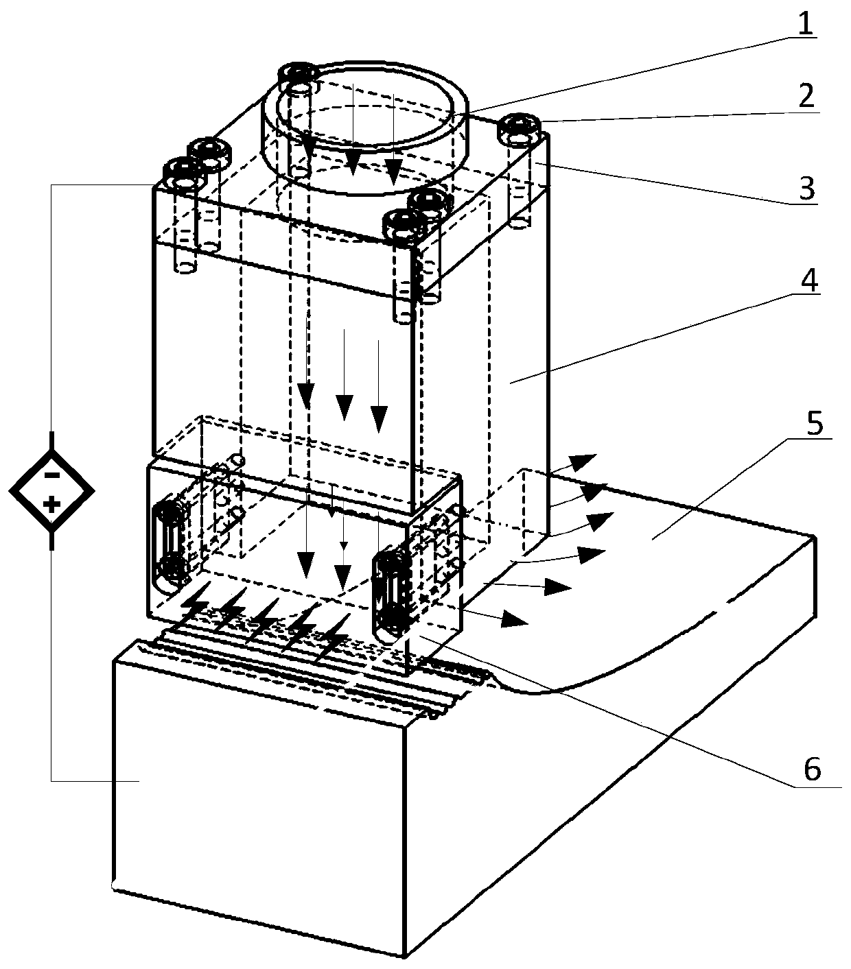
[0031] figure 1 In the schematic diagram of continuous EDM electrolysis shown in the diagram, the pipeline of the electrolyte tank is connected to the tool through the electrolyte inlet pipe 1 and the connecting cover 3, and the connecting cover 3, electrolytic electrode 4 and copper-tungsten alloy EDM electrode 6 use hexagon socket screws 2 connections. One side of the copper-tungsten alloy EDM electrode 6 is the rake face, which ensures that the copper-tungsten alloy EDM electrode 6 first performs EDM machining on the surface of the workpiece to be processed during horizontal feeding.

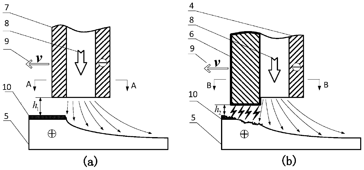
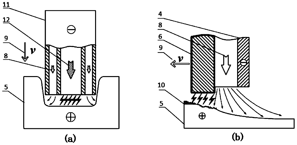
[0032] figure 2 Shown is a schematic diagram of the comparison between electrolytic machining and continuous EDM. from figure 2 It can be seen from (a) that when the processing tool moves horizontally, there is a large initial processing gap between the ordinary electrolysis electrode 7 and the workpiece surface to be processed h 1 , to ensure that processed products can be quickly dis...


PUM


Abstract

The invention relates to an electric spark and electrolytic continuous machining method and tool for efficient plane milling, and belongs to the field of electric spark and electrolytic machining. A cathode of the tool is mainly formed by combining a copper-tungsten alloy electric spark electrode and a stainless steel electrolytic electrode. The initial machining gap of the copper-tungsten alloy electric spark electrode and the to-be-machined surface of a workpiece is set to be a small value, when a large voltage is applied, air in the machining gap is subjected to breakdown, generated electric sparks rapidly remove an oxidation layer and a large number of metal bodies on the surface of the alloy workpiece in a corrosion manner, and the time needed for oxidization layer removal in subsequent electrolytic machining is saved; and then materials are further efficiently removed by the electrolytic electrode through the electrolytic function, and the uneven surface subjected to electric spark machining is subjected to electrolytic machining to be level and smooth. Through electric spark and electrolytic continuous machining, titanium alloy materials can be efficiently removed, and the significance on improving the titanium alloy machining efficiency is achieved.

Description

technical field [0001] The invention relates to an EDM continuous machining method and tool for efficiently milling planes, belonging to the field of EDM. Background technique [0002] With the development of science and technology, a large number of high-temperature alloys, titanium alloys and other metal materials are used in modern aviation, aerospace, shipbuilding and other industrial fields. For example, GH4169 alloy accounts for 34%, 56% and 57% of the total weight of CF6 engine, CY2000 engine and PW4000 engine respectively, and titanium alloy accounts for 41% of the total materials used in the fourth-generation fighter F-22. However, due to the influence of some inherent characteristics of these materials, such as poor thermal conductivity, high strength, and high hardness, the temperature in the processing area is high during machining, and the cutting force is large, which is likely to cause tool wear. Technology presents many challenges. [0003] The principle of...

Claims


Application Information

Patent Timeline
Patent Type & Authority Applications(China)
IPC IPC(8): B23H5/02B23H5/10B23H5/14
CPCB23H5/02B23H5/10B23H5/14
Inventor 曲宁松刘洋赵梓淇谢洲
Owner NANJING UNIV OF AERONAUTICS & ASTRONAUTICS
Why Eureka
Try Eureka