Tunable slow light device based on phase change material, its preparation method and application

A technology of phase change materials and devices, applied in instruments, optics, nonlinear optics, etc., can solve the problems of limited modulation band, no modulation space, single modulation method, etc. Wide frequency range effect

Active Publication Date: 2021-04-02
INST OF PHYSICS - CHINESE ACAD OF SCI
View PDF3 Cites 1 Cited by
  • Summary
  • Abstract
  • Description
  • Claims
  • Application Information

AI Technical Summary

Problems solved by technology

[0004] At present, the existing slow light devices are mostly limited to passive devices that cannot be modulated, that is, once the device is fabricated, its performance is fixed and there is no modulation space, which brings huge restrictions to the practical application of slow light
In a small number of partially tunable slow-light devices, restricted by factors such as material selection and device preparation methods, the modulation band of the device is limited and the modulation method is single, which is not conducive to the integration and application of slow-light devices.
The above problems severely limit the further promotion of slow light devices, so new methods are needed to obtain wide-spectrum range, multi-method tunable slow light devices

Method used


Image

  • Tunable slow light device based on phase change material, its preparation method and application
  • Tunable slow light device based on phase change material, its preparation method and application
  • Tunable slow light device based on phase change material, its preparation method and application

Examples


Embodiment 1

[0075] This embodiment is used to illustrate the preparation method of the tunable slow light device of the present invention.

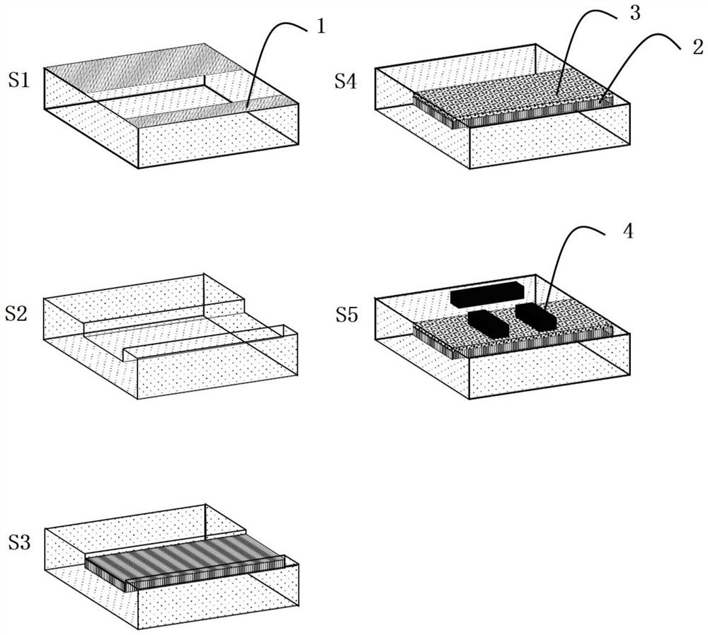
[0076] figure 1 A process flow diagram of the tunable slow light device prepared in Example 1 of the present invention is shown.

[0077] Step S1. Spin-coat photoresist 1 on a clean and transparent dielectric substrate, and obtain a periodic strip structure by exposure or other means; the dielectric substrate is a low-loss medium that can transmit light in the desired response band, including quartz , silicon wafers, sapphire substrates, etc.

[0078] Step S2. Etching grooves from the periodic strip structure described in step S1; the depth of the grooves is consistent with the thickness of the subsequent film deposition. Select an appropriate etching method according to the material of the dielectric substrate, which can be dry etching technology or physical and chemical etching.

[0079] Step S3. Deposit the phase-change material 2 and the diel...

Embodiment 2-3

[0097] This embodiment is used to illustrate the preparation method of the tunable slow light device of the present invention.

[0098] Using the same method as in Example 1, the only difference is that the raw materials are replaced, and an adjustable slow light device can also be obtained, and its materials and properties are shown in the following table.

[0099] Table 1 Preparation and properties of different tunable slow light devices

[0100]

[0101] The deposition conditions of the dielectric protection layer silicon oxide and aluminum oxide in the foregoing embodiments are as follows:

[0102] Among them, silicon oxide deposition requires a plasma-enhanced chemical vapor deposition system (System100 PECVD, Oxford Instruments, UK). The reaction gas and ratio used for silicon oxide deposition are SiH4:N2O:N2=10sccm:327sccm:1000sccm, deposition temperature 110°C, power 10W, pressure 650mTorr, deposition rate about 2nm / s. The deposition of alumina requires an atomic ...


PUM

PropertyMeasurementUnit
widthaaaaaaaaaa
depthaaaaaaaaaa
thicknessaaaaaaaaaa

Abstract

The invention discloses a phase-changing material-based adjustable slow light device. The adjustable slow light device comprises a dielectric substrate, a phase-changing material, a dielectric protection layer and a metal structure which are sequentially arranged. The invention also provides fabrication method and application of the phase-changing material-based adjustable slow light device. The phase-changing material and a metal periodic pattern structure are combined, and control of slow light of the device is achieved by various stimulation means such as light, power and by means of various advantages of wide dielectric constant change frequency range, large change quantity and versatile phase-changing conditions of the phase-changing material. Moreover, the device also has the characteristics of wide integration, wide working frequency range and processing flexibility.

Description

technical field [0001] The invention relates to the field of optical devices, in particular to an adjustable slow-light device based on a phase change material and its preparation method and application. Background technique [0002] The slow light effect is an abnormal physical phenomenon existing in high dispersion devices and media. One of the methods to achieve slow light is to design a periodic structure on the dielectric material, and use the resonance of the structure to cause a drastic change in the velocity of the resonant center group to generate slow light. Among them, the most commonly used method is Electromagnetic Induced Transparency (EIT) technology, and the selected structure is the EIT-like structure. At present, the slow light effect has unique research and practical value in scientific fields such as quantum optics and nonlinear optics, as well as application fields such as optical information storage and optical switches. [0003] In recent years, modu...

Claims


Application Information

Patent Timeline
Patent Type & Authority Patents(China)
IPC IPC(8): G02F1/01G02F1/00
CPCG02F1/0009G02F1/0102
Inventor 顾长志李策朱维张忠山李俊杰
Owner INST OF PHYSICS - CHINESE ACAD OF SCI
Why Eureka
Try Eureka