Double-switch type DC/DC converter circuit topological structure

A circuit topology and double-switch technology, which is applied in the direction of converting DC power input to DC power output, instruments, photovoltaic power generation, etc., can solve the problems of large loss, large volume, and low efficiency

Active Publication Date: 2020-03-31
CSSC SYST ENG RES INST
View PDF8 Cites 2 Cited by
  • Summary
  • Abstract
  • Description
  • Claims
  • Application Information

AI Technical Summary

Problems solved by technology

However, when the current DC/DC converter achieves high gain, there

Method used


Image

  • Double-switch type DC/DC converter circuit topological structure
  • Double-switch type DC/DC converter circuit topological structure
  • Double-switch type DC/DC converter circuit topological structure

Examples


Embodiment Construction

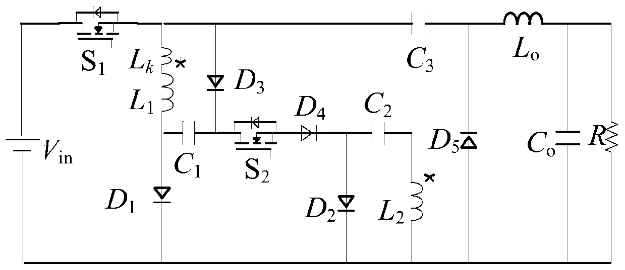
[0015] The circuit topology of the dual-switch DC / DC converter of the present invention includes the input power supply V in , power switch tube S 1 and S 2 , coupled inductor primary inductance L 1 , Coupled inductor secondary inductance L 2 , Coupled inductor leakage inductance L k , Diode D 1 、D 2 、D 3 、D 4 、D 5 , capacitance C 1 、C 2 、C 3 , the output filter capacitor C o , Output filter inductance L o and output load R. Power switch tube S 1 The gate is connected to the control signal voltage V gs1 , switch tube S 1 The drain is connected to the input voltage V in , the source is connected to the primary side of the coupled inductor. Power switch tube S 2 The gate is connected to the control signal voltage V gs2 , switch tube S 2 Drain Connection Capacitance C 1 , the source is connected to the diode D 4 anode.

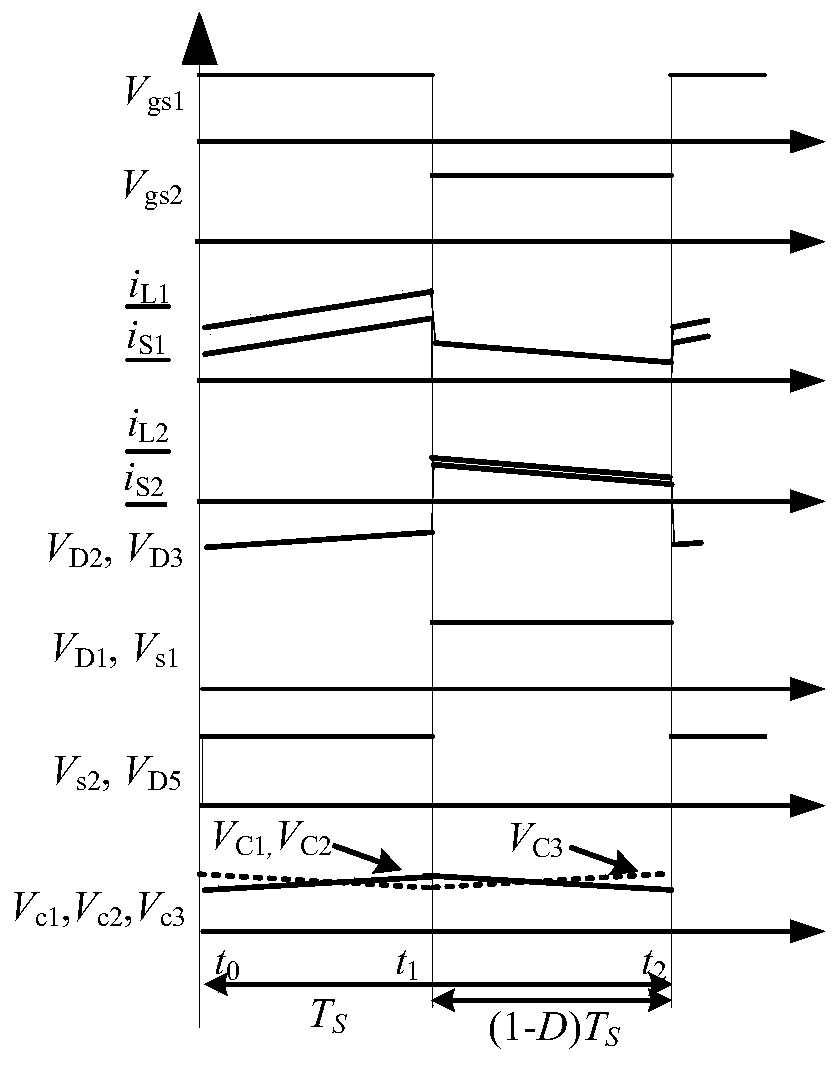
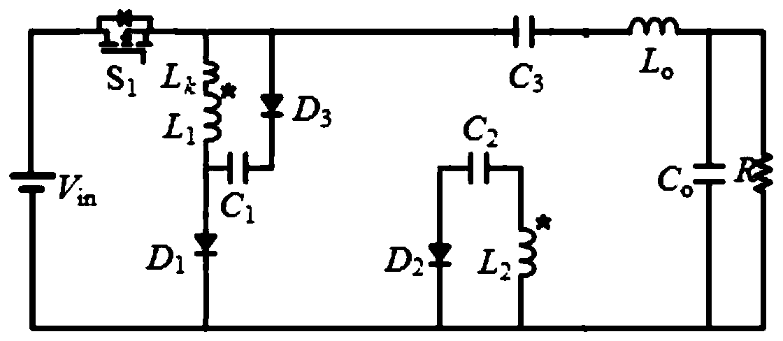
[0016] implementation, such as figure 1 and figure 2 As shown, among them, the power switch tube S 1 , capacitance C 3 , Output filt...


PUM


Abstract

According to the double-switch type DC/DC converter circuit topological structure, through the design of different turn ratios of the primary side and the secondary side of the coupling inductor, charging and discharging of the capacitor C1 and the capacitor C2 and leakage inductance energy recovery in the working process, the converter loss is reduced and the efficiency is improved while the high-voltage gain of the converter is realized. Besides, the boost converter is relatively simple in circuit structure, few in circuit working modes, low in device voltage stress, capable of achieving coupling inductance primary and secondary side energy and leakage inductance energy feedback, and suitable for a boost converter system between the output side of a photovoltaic cell and the micro-grid direct-current bus voltage.

Description

technical field [0001] The invention belongs to the technical field of high-frequency switching converters, and in particular relates to a dual-switch DC / DC converter circuit topology. Background technique [0002] With the continuous progress of society and rapid economic development, global energy consumption is increasing, and the amount of fossil energy storage is decreasing. In addition, environmental problems such as air pollution caused by the combustion of fossil energy have begun to affect people's daily life, threatening human survival and natural ecological security. With the continuous development of science and technology and the continuous popularization of concepts such as green and environmental protection, many new renewable and clean energy sources such as wind energy, solar energy, and biomass energy have been developed and utilized by humans. New energy technologies are developing rapidly and gradually replacing fossil fuels. energy. In addition, with t...

Claims


Application Information

Patent Timeline
IPC IPC(8): H02M3/158
CPCH02M3/158H02M1/0048Y02E10/56Y02B70/10
Inventor 张智杰杨森蔡道萌杜会卿蔡宗举张滨刘玉明孙科孙曦冉杨杰苗春晖
Owner CSSC SYST ENG RES INST
Why Eureka
Try Eureka