Method and testing device for catalytic pyrolysis treatment of oil-based drilling cuttings produced in shale gas exploitation

A technology for shale gas exploitation and oil-based drilling cuttings, which is applied in the field of catalytic pyrolysis treatment method and test device for oil-based drilling cuttings for shale gas exploitation, and can solve the problem of low recovery rate of valuable products, large energy consumption, reduction of the cost, etc. problems, to achieve the effect of recycling resources, reducing pollution and reducing content

Pending Publication Date: 2020-04-10
CHONGQING TECH & BUSINESS UNIV
View PDF8 Cites 3 Cited by
  • Summary
  • Abstract
  • Description
  • Claims
  • Application Information

AI Technical Summary

Problems solved by technology

[0006] The purpose of the present invention is to provide a catalytic pyrolysis treatment method for oil-based drilling cuttings in shale gas exploitation; to solve the disadvantages of high energy consumption and low recovery rate of valuable products (petroleum hydrocarbons) in the current pyrolysis method , the use of urban waste incineration fly ash as a catalyst can not only promote the cracking of heavy macromolecular petroleum hydrocarbons, but also further reduce the content of petroleum hydrocarbons in oil-based drilling cuttings after pyrolysis, which not only reduces pollution, but also maximizes the recovery of resources, achieving Simultaneous treatment of two hazardous wastes

Method used


Image

  • Method and testing device for catalytic pyrolysis treatment of oil-based drilling cuttings produced in shale gas exploitation
  • Method and testing device for catalytic pyrolysis treatment of oil-based drilling cuttings produced in shale gas exploitation
  • Method and testing device for catalytic pyrolysis treatment of oil-based drilling cuttings produced in shale gas exploitation

Examples


Embodiment 1

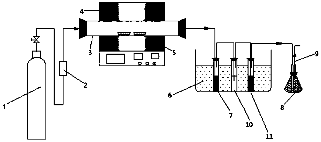
[0027] Two corundum boats were placed in the S01 tube furnace, and each corundum boat was filled with 10 g of oil-based drilling cuttings samples after natural air drying, and the catalyst addition ratio was 10%, that is, 1 g. There are 20 g of samples and 2 g of catalysts in the tube furnace. Introduce nitrogen into the pipeline, set the air flow rate to 0.1L / min, gradually increase the temperature from room temperature to 550°C, and set the holding time after reaching the final temperature to 40min;

[0028] S02 Pass the pyrolysis steam generated in the pipeline into the three-stage condensing device equipped with pyrolysis steam absorbent, and pass the part not absorbed by acetone into the tail gas receiving bottle equipped with tail gas absorption liquid, and the tail gas absorption liquid 5% HNO 3 solution and 10% H 2 o 2 The solution is fully mixed according to the volume ratio of 1:1; the tail gas not absorbed by the tail gas absorption liquid is discharged into the ...

Embodiment 2

[0032] Two corundum boats were placed in the S01 tube furnace, and each corundum boat was filled with 10 g of oil-based drilling cuttings samples after natural air drying, and the catalyst addition ratio was 5%, ie 0.5 g. There are 20 g of samples and 1 g of catalyst in the tube furnace. Introduce nitrogen into the pipeline, set the air flow rate to 0.2L / min, gradually increase the temperature from room temperature to ℃, and set the holding time after reaching the final temperature to 60min;

[0033] S02 Pass the pyrolysis steam generated in the pipeline into the three-stage condensing device equipped with pyrolysis steam absorbent, and pass the part not absorbed by acetone into the tail gas receiving bottle equipped with tail gas absorption liquid, and the tail gas absorption liquid 4% HNO 3 solution and 12% H 2 o 2 The solution is fully mixed according to the volume ratio of 1:3; the exhaust gas not absorbed by the exhaust gas absorption liquid is discharged into the air....

Embodiment 3

[0035] Two corundum boats were placed in the S01 tube furnace, and each corundum boat was filled with 10 g of oil-based drilling cuttings samples after natural air drying, and the catalyst addition ratio was 15%, that is, 1.5 g. There are 20 g of samples and 3 g of catalyst in the tube furnace. Introduce nitrogen into the pipeline, set the flow rate of nitrogen to 0.08L / min, gradually increase the temperature from room temperature to ℃, and set the holding time after reaching the final temperature to 60min;

[0036] S02 Pass the pyrolysis steam generated in the pipeline into the three-stage condensing device equipped with pyrolysis steam absorbent, and pass the part not absorbed by acetone into the tail gas receiving bottle equipped with tail gas absorption liquid, and the tail gas absorption liquid 6% HNO 3 solution and 9% H 2 o 2 The solution is fully mixed according to the volume ratio of 1:5; the tail gas not absorbed by the tail gas absorption liquid is discharged into...


PUM


Abstract

The invention relates to the field of petrochemical engineering, in particular to a method and a testing device for catalytic pyrolysis treatment of oil-based drilling cuttings produced in shale gas exploitation. The method for catalytic pyrolysis treatment of oil-based drilling cuttings produced in shale gas exploitation in the invention can overcome the defects of high energy consumption, low recovery rate of valuable products (petroleum hydrocarbons) and the like of conventional pyrolysis methods; and since municipal waste incineration fly ash is adopted as a catalyst, cracking of heavy high-molecular petroleum hydrocarbon can be promoted, and the content of petroleum hydrocarbons in pyrolyzed oil-based drilling cuttings can be further reduced, so pollution is reduced, resources are recycled to the maximum extent, and two kinds of hazardous waste are treated at the same time. The invention further provides the testing device for catalytic pyrolysis treatment of oil-based drilling cuttings produced in shale gas exploitation. By means of the device, the recovery rate of valuable products (petroleum hydrocarbons) can be increased.

Description

technical field [0001] The invention relates to the field of petrochemical industry, in particular to a catalytic pyrolysis treatment method and a test device for oil-based drilling cuttings in shale gas exploitation. Background technique [0002] The contradiction between energy supply and demand in the world today is becoming more and more prominent. As the country with the largest shale gas reserves in the world, China hopes to find a breakthrough from this unconventional natural gas to break the energy blockade. Since 2012, Fuling District of Chongqing has been authorized as one of the four national shale gas exploitation and utilization demonstration areas. As of September 2019, the total number of gas wells in the Fuling shale gas field has reached 402, and the cumulative production of shale gas has exceeded 250. billion cubic meters, and the daily gas production can meet the domestic gas needs of more than 35 million households. [0003] However, while shale gas prod...

Claims


Application Information

Patent Timeline
Patent Type & Authority Applications(China)
IPC IPC(8): C10G11/02B01D53/14
CPCB01D53/1487B01D53/1493C10G11/02
Inventor 胥腾屯王里奥黄川王翔李彤
Owner CHONGQING TECH & BUSINESS UNIV
Why Eureka
Try Eureka