Multiple trigger photoresist compositions and method

A photoresist and composition technology, applied in the multi-trigger photoresist process field, can solve the problems of reduced exposure latitude, poor resolution, reduced sensitivity and the like

A photoresist and composition technology, applied in the multi-trigger photoresist process field, can solve the problems of reduced exposure latitude, poor resolution, reduced sensitivity and the like

CN110998437APending Publication Date: 2020-04-10A P G 罗宾森 +4

Image

  • Multiple trigger photoresist compositions and method
  • Multiple trigger photoresist compositions and method
  • Multiple trigger photoresist compositions and method

Examples


Embodiment

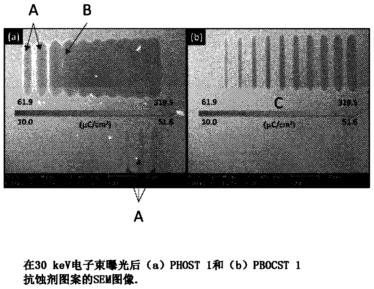
[0064] HMMM used in the examples is hexamethoxymethylmelamine (Sigma Aldrich), PHOST is polyhydroxystyrene (MW = about 2500) synthesized at Warwick University, PBOCST is poly(4-tert-butyl) synthesized at Warwick University oxycarbonyloxystyrene) (MW = about 2500), PGEF is poly((phenylglycidyl ether)-co-formaldehyde) (Huntsman Chemical), PAG is triphenylsulfonium hexafluoroantimonate (Midori Kagaku) .

[0065] PHOST 1: Add 0.50 g of HMMM acid-activated crosslinker, 0.50 g of PHOST and 0.25 g of PAG into 100 mL of propylene glycol monomethyl ether (PGME), and stir at room temperature for 1 hour.

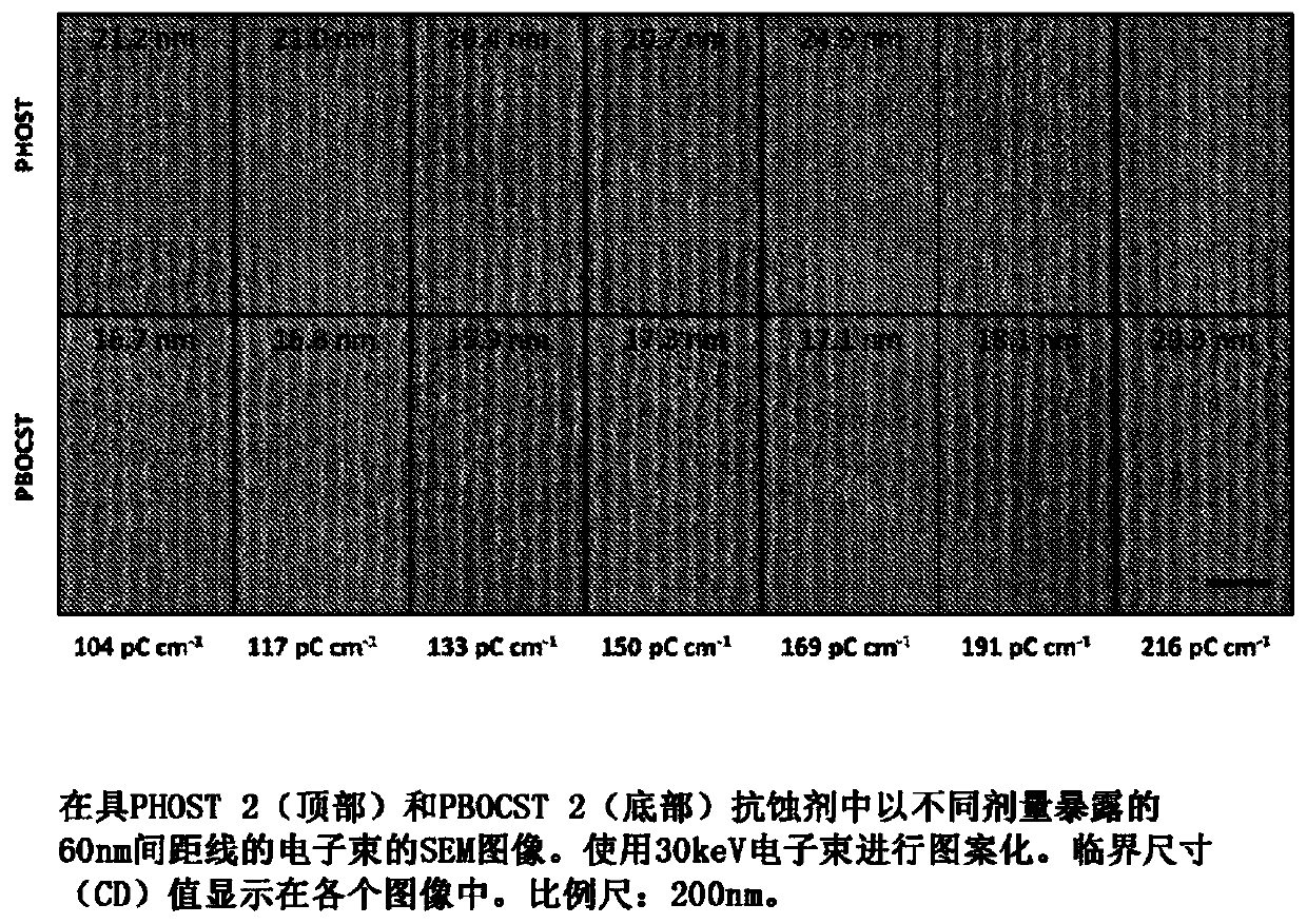
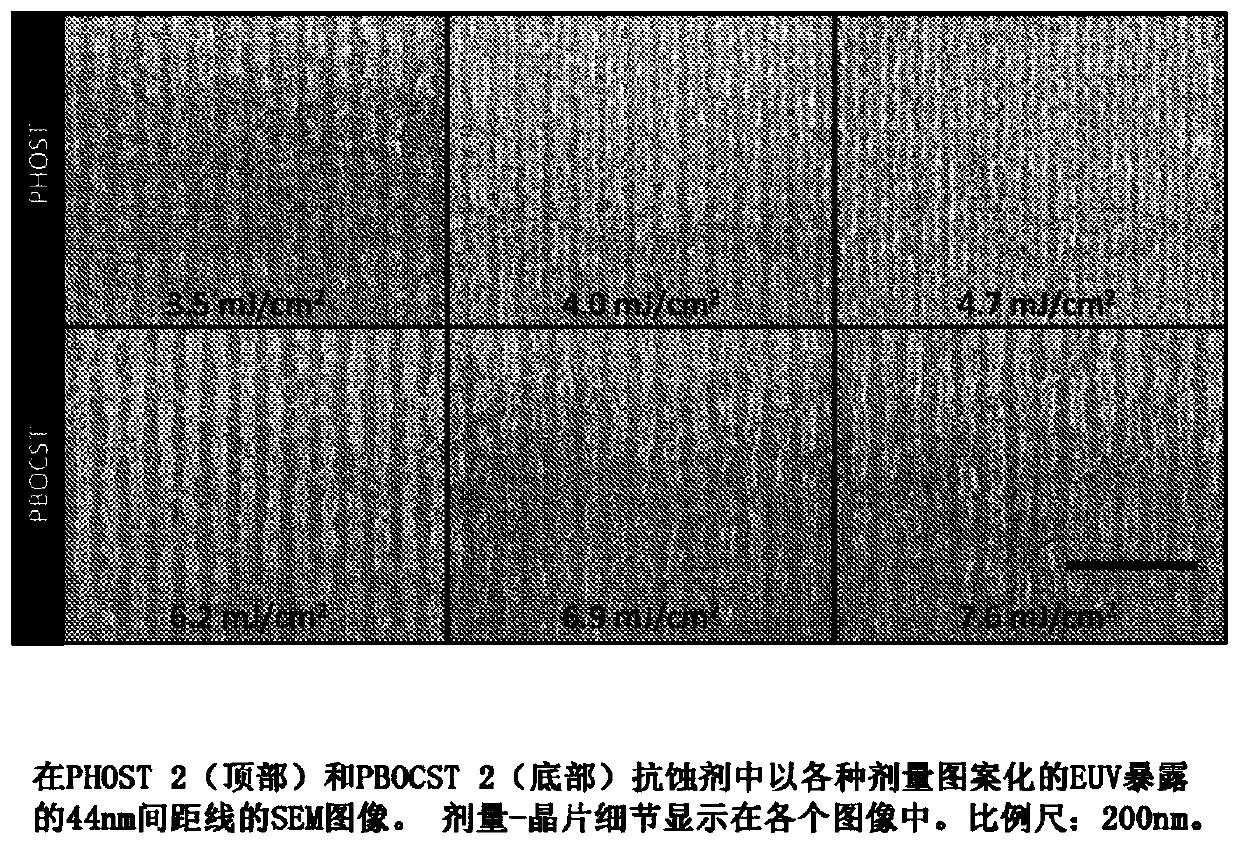
[0066] PHOST 2: Add 0.50 g PGEF acid-activated crosslinker, 0.25 g PHOST and 0.25 g PAG to 100 mL propylene glycol monomethyl ether (PGME), and stir at room temperature for 1 hour.

[0067] PBOCST 1: Replace PHOST with PHOCST, repeat PHOST 1.

[0068] PBOCST 2: Replace HMMM with PGEF, repeat PHOST 2.

[0069] Silicon chips cut from 100 mm wafers (Rockwood Electronic Materials, n-typ...


PUM

PropertyMeasurementUnit
Sensitivityaaaaaaaaaa

Abstract

The present disclosure relates to novel multiple trigger negative working photoresist compositions and processes. The processes involve removing acid-labile protecting groups from crosslinking functionalities in a first step and crosslinking the crosslinking functionality with an acid sensitive crosslinker in a second step. The incorporation of a multiple trigger pathway in the resist catalytic chain increases the chemical gradient in areas receiving a low dose of irradiation, effectively acting as a built in dose depend quencher- analog and thus enhancing chemical gradient and thus resolution, resolution blur and exposure latitude. The photoresist compositions and the methods are ideal for fine pattern processing using, for example, ultraviolet radiation, beyond extreme ultraviolet radiation, extreme ultraviolet radiation, X-rays and charged particle rays.

Description

technical field [0001] The present invention relates to novel negative photoresist compositions and methods of use thereof. The present invention also relates to a multi-trigger photoresist process that allows improvements in contrast, resolution and / or line edge roughness without sacrificing sensitivity in some systems. The photoresist compositions and methods of the present disclosure are ideal for fine pattern processing using, for example, ultraviolet radiation, extreme ultraviolet radiation, extreme extreme ultraviolet radiation, X-rays, and charged particle radiation exposure. Background technique [0002] As is well known in the industry, manufacturing processes of various electronic or semiconductor devices such as ICs, LSIs, etc. involve fine patterning of a resist layer on the surface of a substrate material such as a semiconductor silicon wafer. This fine patterning process is traditionally performed by photolithography, where the substrate surface is uniformly c...

Claims


Application Information

Patent Timeline
10 Apr 2020
Publication
CN110998437A
IPC
G03F7/004
CPC
G03F7/0226; G03F7/0233; G03F7/038; G03F7/322; C08L101/06; G03F7/0382; G03F7/325; G03F7/0045
Inventors
A·P·G·罗宾森; A·麦克兰德