Hydrothermal or pyrohydrolysis tail gas resource utilization system and hydrothermal or pyrohydrolysis tail gas resource utilization method

A technology of resource utilization and thermal hydrolysis, applied in chemical instruments and methods, combustion methods, separation methods, etc., can solve problems such as tail gas odor, achieve convenient management, save investment, and reduce land occupation

Inactive Publication Date: 2020-04-14
四川深蓝环保科技有限公司
View PDF8 Cites 4 Cited by
  • Summary
  • Abstract
  • Description
  • Claims
  • Application Information

AI Technical Summary

Problems solved by technology

[0005] The purpose of the present invention is to address the above problems, to provide a hydrothermal or thermal hydrolysis tail gas resource utilization system and method, to solve the problem of tail gas odor, and to recover the calorific value of hydrothermal waste gas

Method used


Image

  • Hydrothermal or pyrohydrolysis tail gas resource utilization system and hydrothermal or pyrohydrolysis tail gas resource utilization method
  • Hydrothermal or pyrohydrolysis tail gas resource utilization system and hydrothermal or pyrohydrolysis tail gas resource utilization method
  • Hydrothermal or pyrohydrolysis tail gas resource utilization system and hydrothermal or pyrohydrolysis tail gas resource utilization method

Examples


Embodiment 1

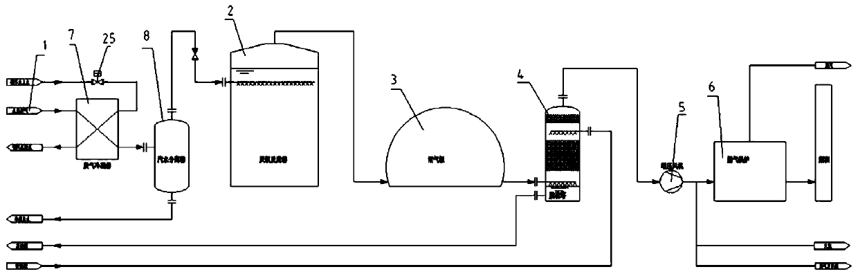
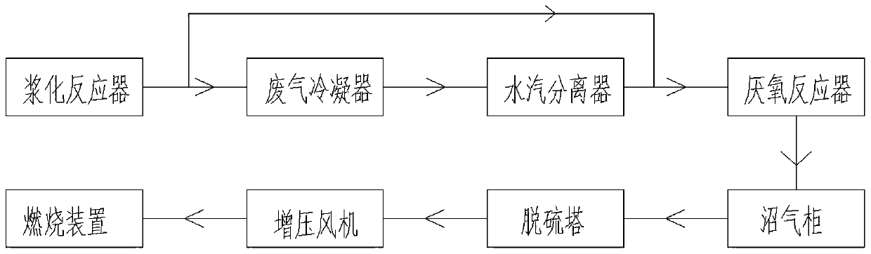
[0046] Such as figure 1 and 5 As shown, a hydrothermal or thermal hydrolysis tail gas resource utilization system includes a slurry reactor 1, an anaerobic reactor 2, a biogas tank 3 and a desulfurization tower 4; the slurry reactor 1 and anaerobic reactor 2 communicated, the anaerobic reactor 2 is communicated with the biogas cabinet 3; the biogas cabinet 3 is communicated with the desulfurization tower 4; it also includes a booster fan 5 and a combustion device 6; the gas inlet of the booster fan 5 is connected with the desulfurization tower The gas outlet of 4 is connected through through, and a check valve is provided between the gas inlet of the booster fan 5 and the gas outlet of the desulfurization tower 4, and the booster fan 5 is connected with the combustion device 6 .

[0047] The desulfurization tower 4 is a wet desulfurization tower, and the desulfurizing agent of the desulfurization tower is sodium carbonate, which comes from the lean liquid tank, and the rich l...

Embodiment 2

[0057] Such as figure 1 and 5 As shown, a hydrothermal or thermal hydrolysis tail gas resource utilization system includes a slurry reactor 1, an anaerobic reactor 2, a biogas tank 3 and a desulfurization tower 4; the slurry reactor 1 and anaerobic reactor 2, the anaerobic reactor 2 communicates with the biogas tank 3; the biogas tank 3 communicates with the desulfurization tower 4.

[0058] A waste gas condenser 7 and a steam-water separator 8 are arranged between the slurry reactor 1 and the anaerobic reactor 2; the waste gas outlet of the slurry reactor 1 is connected with the gas inlet of the waste gas condenser 7, and the waste gas condenser The gas outlet of 7 is connected with the gas inlet of anaerobic reactor 2, and a check valve is arranged between the gas outlet of exhaust gas condenser 7 and the gas inlet of anaerobic reactor 2, and the gas inlet of described anaerobic reactor 2 is low At the working liquid level of the anaerobic reactor 2; the water inlet of the...


PUM


Abstract

The invention discloses a hydrothermal or pyrohydrolysis tail gas resource utilization system, which comprises a slurrying reactor, an anaerobic reactor, a biogas cabinet and a desulfurizing tower, wherein the slurrying reactor is communicated with the anaerobic reactor, the anaerobic reactor is communicated with the biogas cabinet, the biogas cabinet is communicated with the desulfurizing tower,a waste gas condenser and a steam-water separator are arranged between the slurrying reactor and the anaerobic reactor, the waste gas outlet of the slurrying reactor is connected with the gas inlet ofthe waste gas condenser, the gas outlet of the waste gas condenser is connected with the gas inlet of the anaerobic reactor, a check valve is arranged between the gas outlet of the waste gas condenser and the gas inlet of the anaerobic reactor, and the gas inlet of the anaerobic reactor is lower than the working liquid level of the anaerobic reactor. According to the invention, the hydrothermal waste gas of an anaerobic reaction needing heat is directly connected with an anaerobic reactor, and the hydrothermal waste gas of an anaerobic reaction doing not need heat passes through a waste gas condenser and a steam-water separator and then is connected with the anaerobic reactor.

Description

technical field [0001] The invention relates to the technical field of odor treatment, in particular to a hydrothermal or thermal hydrolysis tail gas resource utilization system and method. Background technique [0002] In recent years, under the influence of national energy conservation and emission reduction and active fiscal policies, urban sewage treatment has developed rapidly, and the residue (urban sludge) produced after sewage collection and treatment and effluent discharge reaches the standard. The moisture content of the sludge is about 80%, mainly composed of low-level organic substances such as amino acids, humic acids, bacteria and their metabolites, polycyclic aromatic hydrocarbons, heterocyclic compounds, organic sulfides, volatile odorous substances, organic fluorides, etc. . In addition, it also contains inorganic sand and heavy metals such as mercury, cadmium, and lead. If the sludge is not properly disposed of, it will lead to secondary pollution, making...

Claims


Application Information

Patent Timeline
Patent Type & Authority Applications(China)
IPC IPC(8): B01D53/48B01D53/52B01D53/78B01D53/84B01D53/96F23G7/06
CPCB01D53/343B01D53/48B01D53/52B01D53/78B01D53/84B01D53/96F23G7/06B01D2251/304B01D2251/606B01D2258/05Y02A50/20
Inventor 谢非张超邓舟荀锐李刚夏洲曹宁
Owner 四川深蓝环保科技有限公司
Why Eureka
Try Eureka