Metal foil winding type vacuum coating equipment

A vacuum coating and metal foil strip technology, which is applied in vacuum evaporation coating, metal material coating process, sputter coating, etc., can solve the problem of correcting coating process parameters, poor firmness and reliability of the entire roll of foil strip, and process Unreliable and other problems, achieve uniform etching, ensure color uniformity and consistency

Pending Publication Date: 2020-04-24
DONGGUAN HUICHENG VACUUM TECH
View PDF2 Cites 0 Cited by
  • Summary
  • Abstract
  • Description
  • Claims
  • Application Information

AI Technical Summary

Problems solved by technology

At present, there are more prominent problems: such as the unsatisfactory uniformity and stability of the ion plating color of the whole roll of metal foil, the poor firmness and reliability of the coating bonding force of the whole roll of foil, etc.
[0012] 1. There is no special glue removal process before the heating chamber. Since the surface of the polished foil is pasted with protective paper, there will be residual glue after tearing. It is best to have means to remove it before the foil heating process to improve the coating quality. The existing glow discharge argon plasma etching effect is not good enough;
[0013] 2. Plasma bombardment etching relies on multiple small arc targets to emit plasma overlapping each other to compensate and it is difficult to obtain good uniformity;
[0014] 3. Reactive ion coating adopts multiple small circular cathode arcs arranged in an array, and the coating color is not uniform and stable enough, and the process is not reliable enough;
[0015] 4. There is no online real-time monitoring device for the L*a*b* value and color difference of the coating color in the horizontal and vertical directions of the foil strip, and the coating process parameters cannot be corrected in time according to the real-time displayed color difference to ensure color uniformity and consistency

Method used


Image

  • Metal foil winding type vacuum coating equipment
  • Metal foil winding type vacuum coating equipment
  • Metal foil winding type vacuum coating equipment

Examples


Embodiment Construction

[0088] The present invention will be further described in detail below in conjunction with the accompanying drawings.

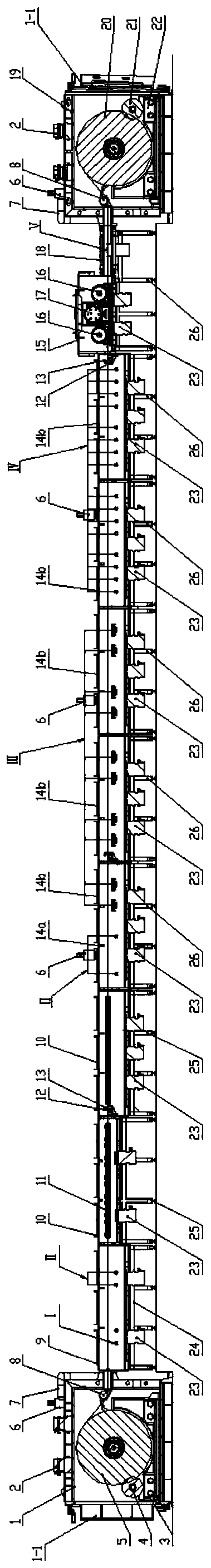
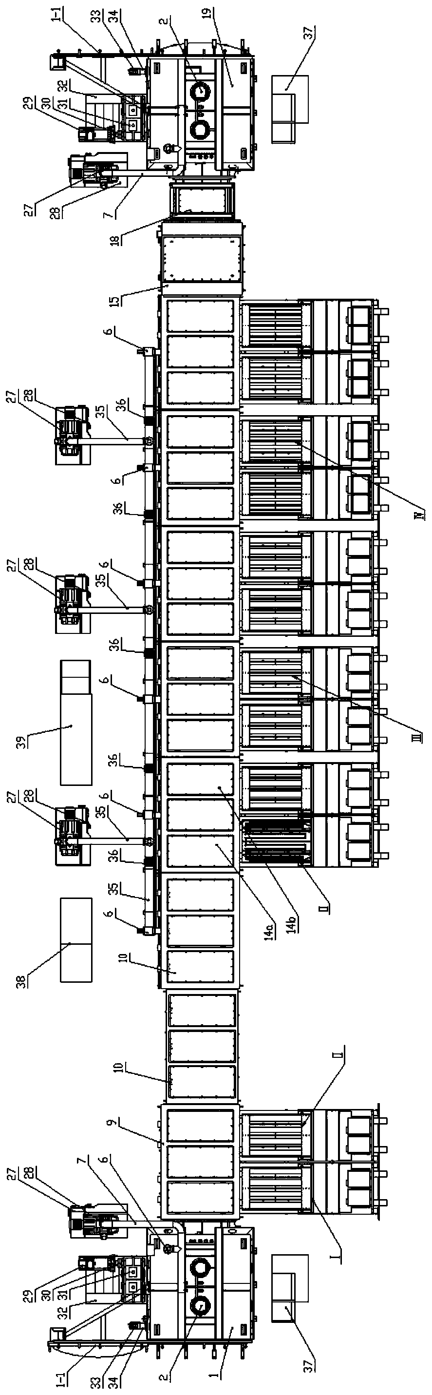
[0089] figure 1 It is a schematic diagram of the main view of the continuous coating production line of ion plating on metal foil strip winding, figure 2 for figure 1 top view diagram.

[0090] The two pictures show the layout structure of the entire production line. The production line is divided into eight cabins connected by vacuum successively. The first cabin is the unwinding cabin 1, the second is the vacuum ion removal cabin 9, and the third is the heating cabin 10. , the fourth is the arc electron source ion bombardment etching chamber 14a, the fifth is the coating chamber 14b, the sixth is the cooling and foil tension adjustment chamber 15, the seventh is the online color detection chamber 18, the eighth For the winding cabin 19.

[0091] There are movable doors at the front and rear of each compartment of the production line for the entry and e...


PUM


Abstract

The invention relates to metal foil winding type vacuum coating equipment. The equipment is equipped with a plasma residual glue removing chamber, the front section is a high-voltage glow discharge etching residual glue removing section, the rear section is a columnar arc light electron source etching section, two windows are disposed on one side of the chamber, and one side of a rack is equippedwith a track. A high-voltage glow discharge etching residual glue removing device comprises an ion residual glue removing high-voltage rod assembly and a first moving trolley, the trolley walks on thetrack, a sealing door bracket composed of a vertical panel and a frame is arranged on the trolley, and a groove-shaped supporting drawer extending to the windows is fixed to the vertical panel. The ion residual glue removing high-voltage rod assembly is fixed on the vertical panel; the columnar arc light electron source etching device assembly comprises a columnar arc light electron source and asecond moving trolley assembly; the columnar arc light electron source is fixed on the vertical panel; the moving trolley moves back and forth on the rail perpendicular to the rack, so that the ion residual glue removing high-voltage rod assembly and the columnar arc light electron source can be pushed into or pulled out of the cavity. The glue removing effect is good.

Description

technical field [0001] The invention relates to a vacuum coating equipment, in particular to a winding vacuum coating equipment for metal foil strips deposited by a flat rectangular cathode arc source. Background technique [0002] After years of development of PVD technology, winding-type vacuum coating equipment has developed rapidly in recent years, and winding-type vacuum coating has been widely used. In the early days, the roll-to-roll vacuum coating equipment was mainly used for the vacuum aluminum coating of the whole roll of plastic film, and it was mostly used in the packaging field. After continuous technological progress, the winding vacuum coating has been applied to the production of SiO2, ITO film, dielectric film and so on. Roll-to-roll coating is a high-speed, high-efficiency continuous coating production method. Tons of reconstituted plastic films are unwound from one end to the other, and the film passes through the coating area at a speed of tens of meter...

Claims


Application Information

Patent Timeline
Patent Type & Authority Applications(China)
IPC IPC(8): C23C14/56C23C14/02C23C14/32C23C14/35C23C14/54
CPCC23C14/022C23C14/325C23C14/352C23C14/547C23C14/562
Inventor 李志荣冯晓庭魏艳玲周锐刘江江邓石新黄雄
Owner DONGGUAN HUICHENG VACUUM TECH
Why Eureka
Try Eureka