
Manufacturing method of high-temperature-resistant negative-temperature-coefficient thermistor

A negative temperature coefficient, thermistor technology, applied in the direction of resistors with negative temperature coefficient, resistance manufacturing, resistors, etc., can solve problems such as unreliable use, and achieve the effect of high use temperature and combined improvement

Inactive Publication Date: 2020-05-01
NANJING SHIHENG ELECTRONICS
View PDF3 Cites 0 Cited by
  • Summary
  • Abstract
  • Description
  • Claims
  • Application Information

AI Technical Summary

Problems solved by technology

[0002] The conventional negative temperature coefficient thermistor (NTC) is formed by tape casting or dry pressing, and two or more transition metal oxides such as cobalt oxide, manganese oxide, nickel oxide, iron oxide, copper oxide and aluminum oxide Doped with transition metal oxides, made into slurry or powder, formed, sintered, and made into electrodes to make NTC thermistor chips, and then made into NTC thermistors by welding, encapsulation or glass encapsulation. In the temperature range of -50-350°C, NTC thermistors have been widely used, but over 350°C, this type of NTC thermistor cannot be used reliably

Method used


Image

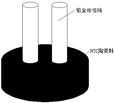
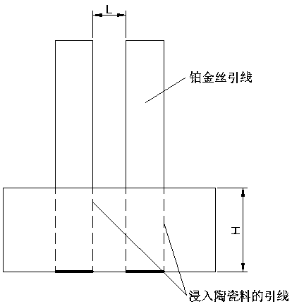
  • Manufacturing method of high-temperature-resistant negative-temperature-coefficient thermistor
  • Manufacturing method of high-temperature-resistant negative-temperature-coefficient thermistor

Examples


Embodiment 1

[0046] Prepare the material according to the molar ratio Mn:Ni:Al=40:50:10, and then feed the material into the planetary ball mill for grinding with the mass ratio of material:ball:water=1:4:0.9, and the speed V=200~220 rpm, Forward and reverse every 30 minutes, grind for 8 hours and discharge. Pour the slurry into a stainless steel tray and place it in an oven for 12±1 hours at a temperature of 80°C±10°C. Pass the dried powder through a 20-mesh stainless steel sieve and crush it, pour it into a high-temperature-resistant porcelain dish and put it in a pre-fired furnace for pre-fired. , to be naturally cooled to 40 ℃ ~ 60 ℃ out. Grind the above-mentioned pre-fired powder for the second time again, the grinding method is the same as the first grinding method, and do not discharge the material after grinding. Add polyvinyl alcohol binder and 0.3% polyacrylamide dispersant according to 2% of the weight of the original powder, and then grind for 30 minutes and discharge to make...

Embodiment 2-3

[0048] The slurry was prepared in the same manner as in Example 1, except that the water in the grinding was replaced by 5% and 20% ethanol aqueous solutions, respectively.

Embodiment 4-6

[0050] The slurry was prepared in the same manner as in Examples 1 to 3, except that no polyvinyl alcohol was added after the secondary grinding, or 1% polyvinyl alcohol was added based on the weight of the dry polyvinyl alcohol powder in the slurry.


PUM


Abstract

The invention discloses a manufacturing method of a high-temperature-resistant negative-temperature-coefficient thermistor, which comprises the following steps of: 1) preparing chip slurry: weighing metal oxide in proportion, and grinding the metal oxide to the required fineness to prepare slurry with the water content of 30-50%, 2) preparing a mold: manufacturing a special mold according to the required chip shape, and coating a mold release agent in the mold, 3) preparing a lead chip slurry combination: arranging two leads as a group according to a required interval, inserting the leads intoa special mold, and pouring chip slurry into the mold, or firstly pouring the chip slurry into the mold, inserting the arranged leads into the mold by a required depth, drying and molding, and demolding, and 4) sintering: sending the lead chip slurry combination into a sintering furnace, and sintering the lead chip slurry combination into porcelain at 1000-1400 DEG C so as to manufacture the high-temperature-resistant negative-temperature-coefficient thermistor. The thermistor element manufactured by the method provided by the invention solves the problem that the negative temperature coefficient thermistor cannot be used in a high-temperature environment.

Description

technical field [0001] The invention belongs to the field of manufacturing electronic components, and in particular relates to a method for manufacturing a high-temperature-resistant negative temperature coefficient thermistor. Background technique [0002] The conventional negative temperature coefficient thermistor (NTC) is formed by tape casting or dry pressing, and two or more transition metal oxides such as cobalt oxide, manganese oxide, nickel oxide, iron oxide, copper oxide and aluminum oxide Doped with transition metal oxides, made into slurry or powder, formed, sintered, and made into electrodes to make NTC thermistor chips, and then made into NTC thermistors by welding, encapsulation or glass encapsulation. In the temperature range of -50-350°C, NTC thermistors have been widely used, but over 350°C, this type of NTC thermistor cannot be used reliably. Contents of the invention [0003] In view of the defects of the thermistor element in the prior art, the presen...

Claims


Application Information

Patent Timeline
Patent Type & Authority Applications(China)
IPC IPC(8): H01C7/04H01C17/28H01C17/30
CPCH01C7/043H01C17/28H01C17/30
Inventor 汪洋
Owner NANJING SHIHENG ELECTRONICS
Learn More