Production process system for preparing machine-made sand through vertical mill

A production process and machine-made sand technology, applied in the direction of solid separation, filter screen, grille, etc., can solve the problems of low efficiency, non-conforming to green production, and poor dust collection effect on site, so as to achieve a high degree of equipment intelligence and benefit large-scale Large-scale production, good environmental protection effect

Pending Publication Date: 2020-06-02
TIANJIN CEMENT IND DESIGN & RES INST +1
View PDF1 Cites 2 Cited by
  • Summary
  • Abstract
  • Description
  • Claims
  • Application Information

AI Technical Summary

Problems solved by technology

[0005] 1. The content of fine powder (less than 0.075mm) is too high in the manufacturing process, resulting in low sand forming rate, high energy consumption, waste of resources and low efficiency;
[0006] 2. There is accumulation of fine powder in the extension of the grinding disc, which causes excessive grinding in the accumulation area, poor operation stability of the vertical mill, poor equipment reliability, and high frequency of shutdown and maintenance;
[0007] 3. In the existing vertical mill, it can be seen from the drawings that tire rollers are used. There is an upward arc-shaped transition surface on the grinding disc of this grinding structure, which leads to poor fluidity of materials on the grinding disc;
[0008] 4. Does not involve auxiliar

Method used


Image

  • Production process system for preparing machine-made sand through vertical mill
  • Production process system for preparing machine-made sand through vertical mill
  • Production process system for preparing machine-made sand through vertical mill

Examples


Embodiment 1

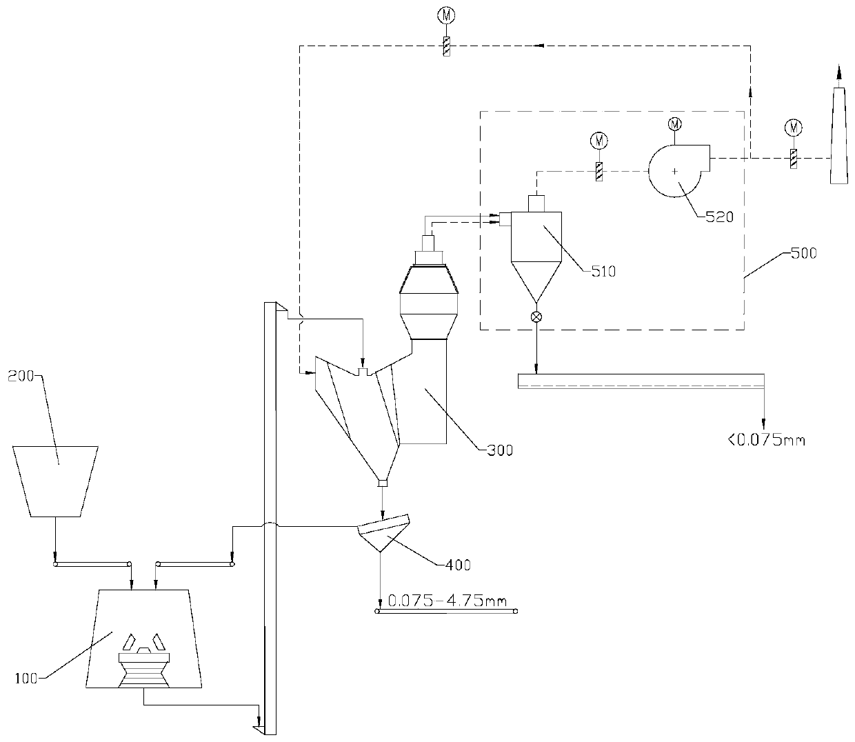
[0042] see figure 1 , the present embodiment provides a production process system for producing machine-made sand by a vertical mill, including a raw material bin 200, a machine-made sand vertical mill 100, a combined powder separator 300, a vibrating screen 400, and a de-powder mechanism 500, the de-powder mechanism 500 Including a cyclone 510 and a circulating fan 520, the outlet of the raw material bin 200 is connected to the material inlet of the machine-made sand vertical mill 100, and the material outlet of the machine-made sand vertical mill 100 is connected to the material inlet of the combined powder separator 300 through a hoist, and the combined powder separator The discharge port at the bottom of the machine 300 is connected with the vibrating screen 400, and the vibrating screen 400 returns the on-screen material to the machine-made sand vertical mill 100. Fan 520 is connected.

[0043] The material is crushed and ground by the machine-made sand vertical mill 100...

Embodiment 2

[0087] Unlike Example 1, see Figure 4 , the material retaining ring in this embodiment is a leaping material retaining ring 140, and the upper part of the leaping material retaining ring 140 is provided with several discharge openings 141, so that the leaping material retaining ring 140 forms a concave-convex structure, so The total area of ​​the discharge opening 141 is 40-60% of the total area of ​​the spanning retaining ring 140 .

[0088] This straddling structure allows some materials to be discharged and some to be blocked, reducing the escape of unground materials and increasing the content of qualified products in the grinding materials. After the material is ground by the grinding roller 110 for a certain period of time, the fine powder accumulates at the corner of the bottom of the retaining ring, forming a slope, which can be used as a stable material layer. After subsequent grinding, the ground material can pass through the formed Slope out of the mill.

[0089]...

Embodiment 3

[0092] Unlike Example 1, see Figure 5 In this embodiment, the outlet of the circulating fan 520 is further provided with a dust collector 600 and a tail exhaust fan 700 in sequence.

[0093] Part of the gas passing through the circulating fan 520 enters the dust collector 600, and after being dedusted by the dust collector 600, it is discharged into the atmosphere through the tail exhaust fan 700 and the chimney. The double fan system composed of circulating fan 520 and exhaust fan 700 is used to increase the effect of on-site dust collection. The dust collector 600 can reduce the dust emission concentration to 5mg / m 3 Below, achieve ultra-clean emissions, which is conducive to environmental protection. At the same time, the setting of the tail exhaust fan 700 is beneficial to the adjustment of the circulating air volume, especially when the moisture content of the grinding material is greater than 2.5%, and the finished product has a high requirement for moisture content (s...


PUM

PropertyMeasurementUnit
Heightaaaaaaaaaa
Heightaaaaaaaaaa
Particle sizeaaaaaaaaaa

Abstract

The invention discloses a production process system for preparing machine-made sand through a vertical mill. The production process system comprises a raw material bin, the machine-made sand verticalmill, a combined powder concentrator, a vibrating screen, a cyclone barrel and a circulating fan, wherein an outlet of the raw material bin is connected with a material inlet of the machine-made sandvertical mill; a material outlet of the machine-made sand vertical mill is connected with a material inlet of the combined powder concentrator; a bottom discharging port of the combined powder concentrator is connected with the vibrating screen; the vibrating screen returns oversize materials to the machine-made sand vertical mill; an air outlet of the combined powder concentrator is connected with the cyclone barrel; an air outlet of the cyclone barrel is connected with the circulating fan; the conical angle of each grinding roller of the machine-made sand vertical mill is not larger than 20degrees; the total projection area of the grinding rollers on a grinding disc is 20%-35% of the area of the grinding disc; a material blocking ring is a through type screening material blocking assembly or a crossing type material blocking ring; and an auxiliary discharging assembly is arranged on the grinding disc and positioned behind each grinding roller in the rotating direction of the grinding disc. The process system is simple in procedure, beneficial to large-scale production and better in environment-friendly effect, and ultra-clean emission can be achieved.

Description

technical field [0001] The invention belongs to the technical field of vertical mill sand production, in particular to a production process system for vertical mill preparation of machine-made sand. Background technique [0002] With the continuous development of the economy, the awareness of environmental protection has gradually become popular among the people. In the field of building materials, concrete is one of the materials used on a large scale. As the aggregate of concrete, sand and gravel play the role of skeleton in concrete. Aggregate is divided into coarse aggregate and fine aggregate. Coarse aggregate refers to aggregate with a particle size greater than 5mm, mainly natural rock or pebble; fine aggregate refers to aggregate with a particle size below 4.75mm, mainly river sand and machine-made sand. Generally speaking, river sand or machine-made sand is called fine sand according to different particle sizes, 0.075-1.18mm is called fine sand, 1.18-2.36mm is cal...

Claims


Application Information

Patent Timeline
IPC IPC(8): B02C21/00B02C23/02B02C15/14B02C23/20B07B9/00B07B1/28B07B1/46B07B7/01B04C9/00
CPCB02C15/14B02C21/00B02C23/02B02C23/20B02C2015/143B04C9/00B07B1/28B07B1/46B07B7/01B07B9/00
Inventor 宋留庆何小龙聂文海徐达融赵剑波杜鑫
Owner TIANJIN CEMENT IND DESIGN & RES INST
Why Eureka
Try Eureka