
Microscopic imaging method based on phase encoding single lens

A phase encoding and microscopic imaging technology, which is applied in the direction of microscopes, instruments, and measuring devices, can solve the problems that the large-space-bandwidth product imaging system cannot work well, the processing quality cannot be guaranteed, and imaging equipment cannot be applied. Simple, easy to build, and the effect of improving imaging resolution

Active Publication Date: 2020-06-02
NANJING UNIV OF SCI & TECH
View PDF16 Cites 4 Cited by
  • Summary
  • Abstract
  • Description
  • Claims
  • Application Information

AI Technical Summary

Problems solved by technology

Among them, the free-form surface method is difficult to eliminate all aberrations because the lens cannot satisfy the optical path difference for all rays of light in a large field of view, and the surface processing is difficult, and the processing quality cannot be guaranteed.
Gradient-index lens method, although capable of eliminating spherical aberration, does not work well in large spatial bandwidth product imaging systems
The metalense method is usually made by electron beam lithography and focused ion beam etching to produce non-periodic nanoscale structures on the lens surface, such as Capasso of Harvard University in "Metalenses at visible wavelengths: Diffraction-limited focusing and subwavelength resolution imaging" In this paper, it is proposed to use a metalens composed of micro-nano structures to realize imaging in the visible light band. However, at present, the diameter of the metalens that can realize single-lens imaging is less than mm, the field of view is small, and the processing is very complicated, which is not yet possible. Applied to common imaging equipment

Method used


Image

  • Microscopic imaging method based on phase encoding single lens
  • Microscopic imaging method based on phase encoding single lens
  • Microscopic imaging method based on phase encoding single lens

Examples


Embodiment Construction

[0022] The present invention will be described in further detail below in conjunction with the accompanying drawings.

[0023] combine Figure 1-Figure 4 , a microscopic imaging method based on a phase-encoded single lens according to the present invention, the specific steps are as follows:

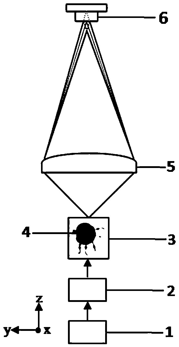
[0024] first step, such as figure 1 The imaging system shown is built, and the imaging system includes a white light LED light source 1, a spatial filter 2, a moving stage 3, a phase-encoding single lens 5, and an image sensor 6 (CCD or CMOS can be selected) arranged in sequence along the optical path. Wherein, the biological sample 4 is set on the mobile stage 3, and the image sensor 6 is located at the conjugate position of the biological sample 4 under G light illumination. The white LED light source 1 is turned on to generate light, which is incident on the biological sample 4 through the spatial filter 2 , and then imaged by the phase-encoded single lens 5 and collected by the ima...


PUM

PropertyMeasurementUnit
refractive indexaaaaaaaaaa

Abstract

The invention discloses a microscopic imaging method based on a phase encoding single lens. The method only adopts one single lens with a phase encoding function for imaging, combines with a subsequent processing algorithm, can realize microscopic imaging resolution capability equivalent to that of an existing precision commercial microscope, and is suitable for portable biological tissue and celldetection under field conditions. Firstly, an imaging system adopts a phase encoding single lens with two aspheric surfaces to image a biological sample, and an image sensor is located at the conjugate position of the biological sample under G light illumination and used for collecting images; and then, the acquired images are processed by adopting an algorithm: respectively executing an automatic focusing algorithm on the acquired images in R / B channels, and reconstructing and recovering the focusing images of the R / B channels; performing high-resolution image reconstruction on the quasi-focus images of the R, G and B channels by adopting a trained kernel function of a generative adversarial neural network (GAN); and finally, performing image matching and color fusion on the reconstructed R / G / B images.

Description

technical field [0001] The invention belongs to the field of microscopic imaging, in particular to a microscopic imaging method based on a phase-coded single lens. Background technique [0002] At present, one of the commonly used detection methods for observing the microscopic world is to use microscopes to visually detect collected biochemical samples, such as phase contrast microscopes, differential interference phase contrast microscopes, fluorescence microscopes, and laser confocal microscopes, which have promoted the level of life science research. With the improvement of higher resolution and imaging quality, it provides a strong imaging basis for disease diagnosis, especially the early diagnosis of major malignant diseases, but they are usually expensive, bulky, and cumbersome, which is not conducive to the field use. [0003] With the development of the times, the field biochemical detection in the field of mobile medical and environmental protection has an increas...

Claims


Application Information

Patent Timeline
Patent Type & Authority Applications(China)
IPC IPC(8): G02B21/36G01N21/84G01N21/01
CPCG02B21/361G02B21/365G01N21/84G01N21/01G01N2021/0112
Inventor 卞殷旭占林沈华张超
Owner NANJING UNIV OF SCI & TECH
Learn More