Photo-thermal heterodyning microimaging detection system and method
A technology of microscopic imaging and detection system, which is applied in measurement devices, material analysis by optical means, instruments, etc., can solve the problems of bleaching, unstable fluorescent labeling signals, and inability to directly image non-fluorescent objects, and achieves improved signal-to-noise. ratio, improve extraction and resolution capabilities, and overcome the effect of direct imaging
- Summary
- Abstract
- Description
- Claims
- Application Information
AI Technical Summary
Problems solved by technology
Method used
Image
Examples
specific Embodiment approach 1
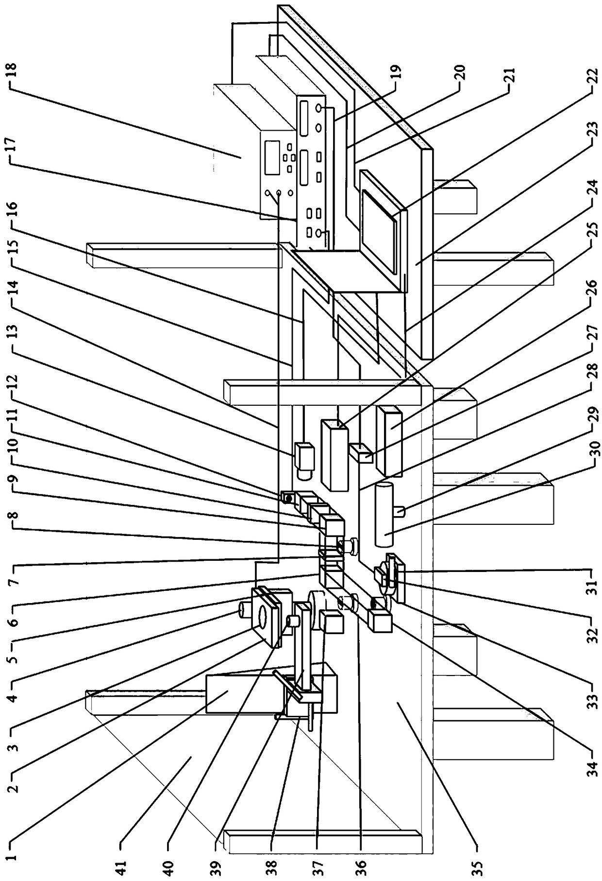
[0024] Specific implementation mode one: as figure 1 As shown, what is described in this embodiment is a photothermal heterodyne microscopic imaging detection system. Chromatic mirror 6, 1 / 4 wave plate 7, cage frame support 8, polarization beam splitter cube 9, 600nm long-pass filter 10, beam splitter 11, avalanche photodiode module 12, CCD camera 13, piezoelectric movement Table control line 14, SMA to BNC line 15, Ethernet line 16, lock-in amplifier SR84417, two-dimensional piezoelectric mobile station controller 18, SMA to BNC line 19, GPIB data line 20, USB control line 21, computer 22, office Table 23, USB data cable 24, 638nm laser 25, 532nm laser 26, acousto-optic modulator driver 27, SMA control line 28, frame support rod 29, 20×beam reducer 30, rotating mobile table 31, acousto-optic modulator 32. Lifting mobile platform 33, mirror one 34, optical platform 35, cage frame connecting rod 36, mirror two 37, three-dimensional mobile platform 38, objective lens cantilever...
specific Embodiment approach 2
[0027] Specific implementation mode two: as figure 1 , figure 2 As shown, a photothermal heterodyne microscopic imaging detection method using the photothermal heterodyne microscopic imaging detection system of the first embodiment, the specific steps of the method are as follows:
[0028] Step 1: Determine the test sample 3 to be measured, clamp and fix it on the two-dimensional piezoelectric mobile platform 2, and the two-dimensional piezoelectric mobile platform 2 controls the horizontal movement of the test sample 3;
[0029] Step 2: first turn on the computer 22, the lock-in amplifier 17, the two-dimensional piezoelectric mobile controller 18, the CCD camera 13, the 638nm laser 25, the 532nm laser 26, and the acousto-optic modulator driver 27;
[0030] Step 3: Control the 638 laser 25 to output excitation light through the computer 22, turn on the 532nm laser 26 at the same time, and then adjust the optical path, so that the two laser beams are combined through the opti...
specific Embodiment approach 3
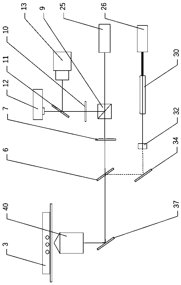
[0035] Specific implementation mode three: as figure 2 As shown, the photothermal heterodyne microscopic imaging detection method described in the second specific embodiment, the optical path propagation sequence in the method is: the excitation light emitted by the 532nm laser 26 passes through the 20× beam reducer 30 to reduce the beam diameter, Entering the acousto-optic modulator 32, through the acousto-optic modulation, the output light becomes modulated light with high-frequency modulation of light intensity; then passes through the dichroic mirror 6 to combine with the probe light, and is focused by the 100×objective lens 40 to act on the detection sample 3 above; the probe light emitted by the 638nm laser 25 first passes through the polarization beam splitter cube 9 to output linearly polarized light, then passes through the 1 / 4 wave plate 7 to realize the circular polarization of the probe light, and combines with the excitation light at the dichroic mirror 6 Work to...
PUM
| Property | Measurement | Unit |
|---|---|---|
| Particle size | aaaaa | aaaaa |
Abstract
Description
Claims
Application Information
 - R&D
- Intellectual Property
- Life Sciences
- Materials
- Tech Scout
- Unparalleled Data Quality
- Higher Quality Content
- 60% Fewer Hallucinations
Browse by: Latest US Patents, China's latest patents, Technical Efficacy Thesaurus, Application Domain, Technology Topic, Popular Technical Reports.
© 2025 PatSnap. All rights reserved.Legal|Privacy policy|Modern Slavery Act Transparency Statement|Sitemap|About US| Contact US: help@patsnap.com


