
Eureka
For R&D, Eureka makes reading and utilizing patents & technical documents easy.
Eureka AIR
Designed for self-driven R&D workflows. Generate viable solutions, solve complex R&D challenges, empower your innovation with AI.

Eureka Materials
Designed for material experts only. Revolutionize your material R&D, from search, analyze, to developing new materials.

TechResearch
Generate reliable direction feasibility study reports for your R&D in just a few steps.

TechSeek
Discover and master advanced knowledge NOW. Basics, ideas, possibilities, all at once.

TechMind
As an expert in R&D Theories, TechMind can generates customized viable solutions instantly.

TechRisk
Analyze your overall solution with one click, know your potential R&D risks in advance.

TechMonitor
Get weekly tech updates, stay abreast of the latest tech innovations and key insights.
Lithium slurry battery storage tank system
A slurry battery and material storage tank technology, applied in the field of slurry battery storage tank system, can solve the problems of increasing manufacturing cost, space occupation and system complexity
- Summary
- Abstract
- Description
- Claims
- Application Information
AI Technical Summary
Problems solved by technology
Method used
Image

Examples
Embodiment 1
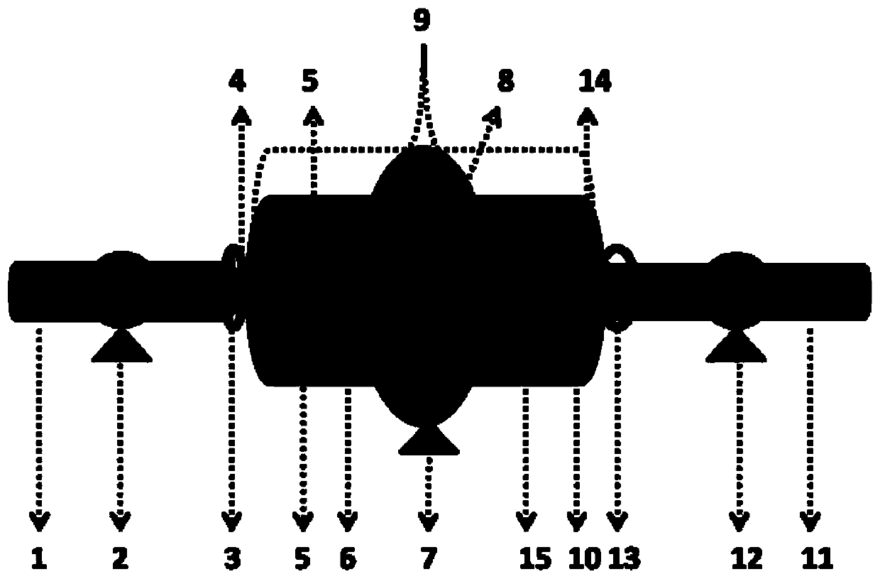
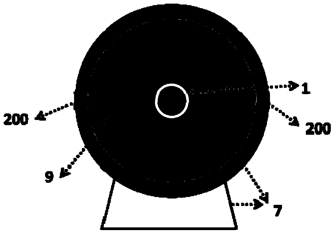
[0028] Such as figure 1 As shown, this implementation case provides a lithium slurry battery storage tank system, including a positive storage tank system and a negative storage tank system, and the positive and negative storage tank systems have the same structure. The concrete storage tank system includes a tank material tank rotating frame 7, a material storage tank 9, a feed pipe 1, a discharge pipe 11, and feed liquid pumps 2 and 12. Wherein the storage tank is equipped with mobile interlayer groups 5 and 8. Wherein, the outside of the slurry tank is made of aluminum-plastic material, the moving spacers 5 and 8 are made of polyethylene material, and the feed pipe 1 and discharge pipe 11 are made of polyethylene material.
[0029] In this case, the inner diameter of the positive and negative storage tanks 9 is 20 cm, and the diameter of the movable partition 8 is 20 cm. The operating mode of the lithium slurry battery is intermittent. The infusion speed of the intermitt...
Embodiment 2
[0033] On the basis of the implementation of Case 1, this case provides the operating mode of the lithium slurry battery as a continuous flow storage tank.
[0034] The positive and negative electrode slurries enter the lithium slurry battery reactor from the discharge port 14 of the positive and negative electrode storage tank 9 by starting the respective liquid pumps of the positive and negative electrodes to perform charge and discharge reactions. The input speed of the liquid pump is adjusted and controlled by the charge and discharge program, and the positive and negative slurry is continuously transported from the positive and negative electrode outlets 14 to the reactor through the positive and negative electrode outlet pipes, and then passes through the feed pipe 1 after reaction. Transported to the feeding chamber 6, with the continuous increase of the slurry in the feeding chamber 6, the mobile interlayer 8 is continuously moved towards the discharge chamber 15 until th...
Embodiment 3
[0037] On the basis of implementation case 1, this case provides several kinds of positive and negative storage tanks, moving interlayer groups 5 and 8, and the constituent materials of the inlet and outlet pipes. In this embodiment, positive and negative storage tanks 9, moving interlayer groups 5 and 8, the constituent material examples of inlet and outlet pipes are assembled in any way and are not limited to these several materials. Composed of proportional composite materials; the materials of moving compartment groups 5 and 8 and the material of the inlet and outlet pipes are made of polyethylene, polypropylene, polyvinylidene fluoride, polytetrafluoroethylene, one or two or more of these materials according to Composite composition in any proportion, as shown in Table 1 and not limited to the combination in Table 1:
[0038] Table 1 Constituent materials of positive and negative electrode storage tanks, mobile interlayer group, and inlet and outlet pipes
[0039] ...
PUM
| Property | Measurement | Unit |
|---|---|---|
| diameter | aaaaa | aaaaa |
Abstract
Description
Claims
Application Information
 - R&D Engineer
- R&D Manager
- IP Professional
- Industry Leading Data Capabilities
- Powerful AI technology
- Patent DNA Extraction
Browse by: Latest US Patents, China's latest patents, Technical Efficacy Thesaurus, Application Domain, Technology Topic, Popular Technical Reports.
© 2024 PatSnap. All rights reserved.Legal|Privacy policy|Modern Slavery Act Transparency Statement|Sitemap|About US| Contact US: help@patsnap.com