Method for electrolysis reuse of alkaline etching waste liquid

An etching waste liquid and alkaline technology, which is applied in the field of alkaline etching waste liquid electrolysis and reuse, can solve the problems of increasing the electrolytic voltage, increasing the resistance of the electrolytic cell, wasting raw materials, etc., achieving a small peak current effect and reducing the generation speed. , the effect of improving recycling efficiency

Pending Publication Date: 2020-06-19
叶旖婷
View PDF10 Cites 5 Cited by
  • Summary
  • Abstract
  • Description
  • Claims
  • Application Information

AI Technical Summary

Problems solved by technology

[0014] Second, because the ammonia water itself is easy to volatilize and become ammonia gas to escape, and the ammonium ions in the electrolyte move to the cathode under the influence of the electric field attraction during the electrolysis process, resulting in the accumulation of ammonium ions near the cathode, resulting in an increase in the local ammonia concentration of the electrolyte. During the electrolysis process, the temperature of the electrolyte is higher than room temperature, which further promotes the volatilization of ammonia and wastes raw materials.
Therefore, the electrolyte near the anode is prone to low ammonia water content, so that there is not enough ammonia and copper ions in the electrolyte near the anode for complexation reaction, and it is difficult to form a soluble copper ammonium complex, so some copper ions It will precipitate in the form of copper sludge and settle on the bottom of the electrolytic cell or the slurry will stick to the anode, which increases the resistance of the electrolytic cell
In this case, electrolysis will increase the necessary electrolysis voltage between the cathode and anode, and waste electric energy.
[0015] Third, the return of the electrolyte after e

Method used


Image

  • Method for electrolysis reuse of alkaline etching waste liquid
  • Method for electrolysis reuse of alkaline etching waste liquid
  • Method for electrolysis reuse of alkaline etching waste liquid

Examples


Embodiment 1

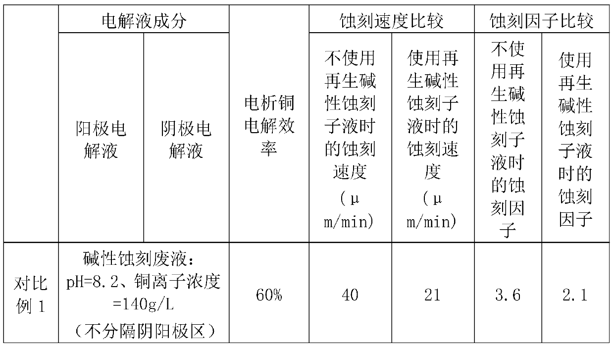
[0057] (1) Use an electrolytic cell composed of an electrolytic cell, an electrolytic power supply, an electrolytic anode and an electrolytic cathode, and separate the electrolytic cell into an anode area and a cathode area by superimposing a ceramic filter plate and a filter cloth;

[0058] Prepare the anolyte and catholyte according to the composition and ratio of the following table-1, and add the anolyte and catholyte to the anode area and the cathode area respectively;

[0059] (2) Start the electrolysis power supply to carry out the electrolysis operation, and deposit metallic copper on the electrolysis cathode;

[0060] (3) After 2 hours of electrolysis, mix the anolyte and catholyte, add 5% water by weight, and then use liquid ammonia to adjust the pH to 11 to form a regenerated alkaline etching sub-liquid, which is recycled for use in Etching production line.

Embodiment 2

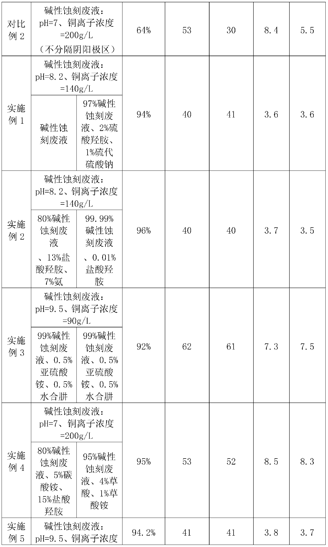
[0062] (1) Use an electrolytic cell consisting of a sealed electrolytic cell, an electrolytic power supply, an electrolytic anode and an electrolytic cathode, and use a PE filter plate to separate the electrolytic cell into an anode area and a cathode area;

[0063]Prepare the anolyte and catholyte according to the composition and ratio of the following table-1, and add the anolyte and catholyte to the anode area and the cathode area respectively;

[0064] (2) Start the electrolysis power supply to carry out the electrolysis operation, and at the same time, the gas generated in the electrolytic cell is pumped out, and metal copper is deposited on the electrolysis cathode, and is manually transferred to the anode area and the cathode area every half an hour. Supplementary volume of anolyte and catholyte with a volume of 5% of the preset liquid level;

[0065] (3) After 2 hours of electrolysis, the anolyte and catholyte were mixed for solid-liquid separation, and then adjusted t...
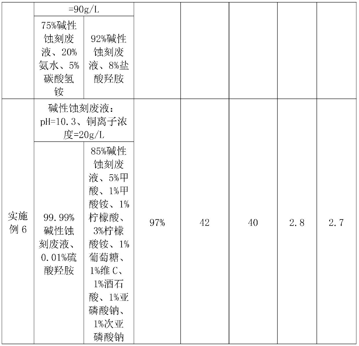
Embodiment 3

[0067] (1) Use an electrolytic cell consisting of a sealed electrolytic cell, an electrolytic power supply, an electrolytic anode and an electrolytic cathode, and use an anion membrane to separate the electrolytic cell into an anode area and a cathode area;

[0068] Prepare the anolyte and catholyte according to the composition and ratio of the following table-1, and add the anolyte and catholyte to the anode area and the cathode area respectively;

[0069] (2) Start the electrolysis power supply to carry out the electrolysis operation, and at the same time, the gas generated in the electrolytic cell is pumped out, and metallic copper is precipitated on the electrolysis cathode, and is automatically detected according to the real-time pH value of the anolyte in the anode area The input and control machine replenishes alkaline etching waste liquid to the anode area, and the automatic detection input and control machine adds reducing agent to the anode area according to the real-...


PUM


Abstract

The invention provides a method for electrolysis reuse of alkaline etching waste liquid. The method comprises the following steps that (1) the alkaline etching waste liquid or mixed liquid of the alkaline etching waste liquid and a reducing agent serves as anode electrolyte to be added into an anode region, and the mixed liquid of the alkaline etching waste liquid and the reducing agent serves ascathode electrolyte to be added into a cathode region; (2) an electrolysis power supply is started for electrolysis operation, and metal copper is separated out on an electrolysis cathode; and (3) according to a specific alkaline etching process, ammonium chloride, ammonia, water and one or more of components contained in other alkaline etching liquid are added into anode liquid and/or cathode liquid after electrolysis operation in the step (2) to prepare regenerated alkaline etching sub-liquid capable of being reused on an alkaline etching production line. According to the method, the electrolysis copper separate-out efficiency can be improved, and the waste liquid can be prepared to form the regenerated alkaline etching sub-liquid capable of maintaining the ideal etching effect after electrolysis reuse.

Description

technical field [0001] The invention belongs to the technical field of post-treatment of etching waste liquid, and in particular relates to a method for electrolytic reuse of alkaline etching waste liquid. Background technique [0002] Etching is an important step in the existing printed circuit board (PCB) fabrication process. Etching refers to chemically removing unnecessary copper on the copper clad substrate with an etchant to form the desired circuit pattern. [0003] At present, commonly used etching solutions for circuit board production include acidic copper chloride etching solution and alkaline copper ammonium chloride etching solution (hereinafter referred to as alkaline etching solution). The main components of the alkaline etching solution are copper salts, ammonium chloride, ammonia water, water, optional carbonates, and optional additives; among them, the carbonates are usually ammonium carbonate and ammonium bicarbonate. In the actual production process, as...

Claims


Application Information

Patent Timeline
IPC IPC(8): C23F1/46C25C1/12C25C7/06
CPCC23F1/46C25C1/12C25C7/06Y02P10/20
Inventor 叶旖婷
Owner 叶旖婷
Why Eureka
Try Eureka