Temperature measurement system and method based on pixelated dual-band narrow-band optical filter array

A narrow-band filter and temperature measurement technology, applied in optical radiation measurement, radiation pyrometry, measurement devices, etc., can solve the problems of large measurement error, low spatial resolution and spatial resolution, and inconvenient integration

Active Publication Date: 2020-06-30
BEIJING INSTITUTE OF TECHNOLOGYGY
View PDF11 Cites 8 Cited by
  • Summary
  • Abstract
  • Description
  • Claims
  • Application Information

AI Technical Summary

Problems solved by technology

Among them, the colorimetric temperature measurement device, one of the radiation temperature measurement methods, has been widely used in recent years. For example, in the Chinese patent with the publication number CN108279071A, a full-field molten pool temperature based on the colorimetric temperature measurement method is disclosed. The field detection system is used to monitor the change of the temperature field of the molten pool in real time. The patent adds a synchronous trigger function to the device, and adds a blackbody furnace calibration to the data processing. However, the dual-camera measurement optical path designed by the patent requires two On the one hand, the cost is high, the whole device is large, and the control and debugging are more complicated. On the other hand, it is difficult to ensure that the two cameras are triggered at the same time when the temperature field is measured by two cameras. The data collected by the two cameras It is difficult to match the positions of the images at the same time. This will be a great choice for high-speed and ultra-high-speed measurement fields such as high-speed rotating turbine blades in engines in aerospace, automotive, and ship engineering, and rapidly changing metal molten pools in additive manufacturing industries. There will be a large measurement error
In the Chinese patent with the publication number CN108871585A, a temperature field measurement system and method based on a single camera is disclosed. The patent uses a high-speed camera for temperature measurement, which meets the requirements of high-speed temperature measurement under special working conditions. In addition, the patent design The spectroscopic system thus realizes single-camera temperature measurement, but the temperature measurement method designed in this patent has...

Method used


Image

  • Temperature measurement system and method based on pixelated dual-band narrow-band optical filter array
  • Temperature measurement system and method based on pixelated dual-band narrow-band optical filter array
  • Temperature measurement system and method based on pixelated dual-band narrow-band optical filter array

Examples


Embodiment 1

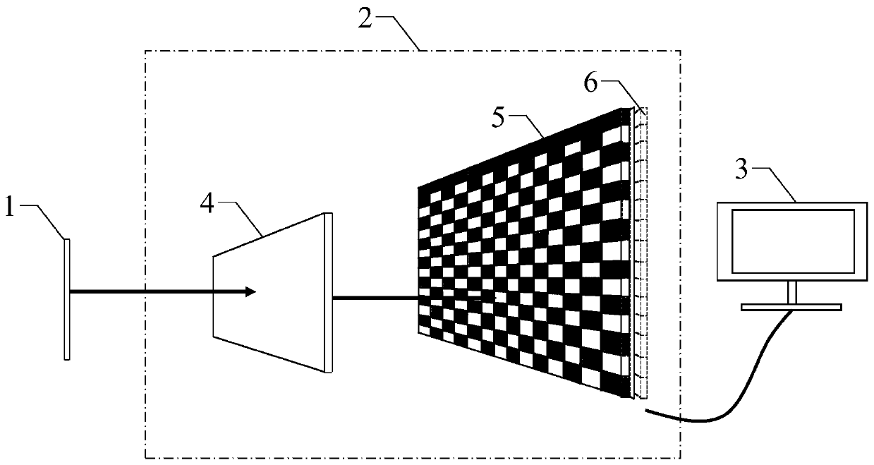
[0060] figure 1 It is a structural schematic diagram of a temperature measurement system based on a pixelated dual-band narrowband filter array in this embodiment, as figure 1 As shown, the present embodiment provides a temperature measurement system based on a pixelated dual-band narrow-band filter array, the temperature measurement system includes a dual-band array image acquisition device 2 and a computing device 3, and the dual-band array image acquisition device 2 and computing device The device 3 is electrically connected;

[0061] In the calibration stage, the dual-band array image acquisition device 2 is used to acquire the grayscale array image of the calibration area of ​​the high-temperature calibration device including the radiation light in the first band and the second band, and the computing device 3 is used to acquire and record the correction parameter matrix and system response parameters matrix;

[0062] In the measurement phase, the dual-band array image ...

Embodiment 2

[0087] This embodiment provides a temperature measurement method based on a pixelated dual-band narrowband filter array, the method includes a calibration phase and a measurement phase performed by a temperature measurement system based on a pixelated dual-band narrowband filter array, and the temperature measurement system Calibration is then used for temperature measurement.

[0088] Figure 6Shown is the flow chart of the calibration stage based on the pixelated dual-band narrowband filter array in this embodiment, as Figure 6 shown, combined with Figure 1-5 , the calibration phase includes:

[0089] Step 2011, direct the dual-band array image acquisition device 2 to the calibration area of ​​the high-temperature calibration device, and use the dual-band array image acquisition device 2 and the image receiving module 101 to acquire the single-band grayscale array image and the dual-band array image of the calibration area of ​​the high-temperature calibration device gr...


PUM


Abstract

The invention discloses a temperature measurement system and method based on a pixelated dual-band narrow-band optical filter array, and relates to the technical field of infrared light side mechanics. The temperature measurement system comprises a dual-band array image acquisition device and a calculation device; in the calibration stage, the dual-band array image acquisition device is used for acquiring a gray scale array image of dual-band radiation light in a calibration area of the high-temperature calibration device, and the calculation device is used for acquiring a correction parametermatrix and a system response parameter matrix; in a measurement stage, the dual-band array image acquisition device is used for acquiring a gray scale array image of dual-band radiation light of an object to be measured, and the calculation device is used for correcting the gray scale array image of the object to be measured, extracting data and calculating a temperature field of the object to bemeasured. According to the invention, the common influence caused by the quality difference of each filtering unit, the lens distortion, the chromatic aberration, the integration error of the filtering units and the pixels and the like is eliminated in the temperature measurement system and the temperature measurement method for the first time, and the precision of the temperature measurement system and method is improved.

Description

technical field [0001] The present invention relates to the technical field of infrared light side mechanics, and more specifically, relates to a temperature measurement system and method based on a pixelated dual-band narrow-band filter array. Background technique [0002] Measuring the surface temperature field of materials is of great significance in aerospace, machinery manufacturing, nuclear energy and other fields. Therefore, having advanced temperature measurement methods is an important condition for promoting the development of aerospace, machinery manufacturing, and nuclear energy fields. important guarantee. [0003] At present, due to the special high-temperature working conditions, the traditional contact temperature measurement not only has a slow response speed and cannot measure the temperature of the whole field, but may also cause damage to the temperature field. Compared with traditional temperature measurement methods, non-contact temperature measurement...

Claims


Application Information

Patent Timeline
IPC IPC(8): G01J5/00G06T7/80G06T7/90G06F17/16
CPCG01J5/0003G06T7/80G06T7/90G06F17/16G01J2005/0077G01J5/80
Inventor 刘战伟封伟赵家业郝策谢惠民刘胜
Owner BEIJING INSTITUTE OF TECHNOLOGYGY
Why Eureka
Try Eureka