


Quick Research
Generate reliable direction feasibility study reports for your R&D in just a few steps.

Technical Q&A
Discover and master advanced knowledge NOW. Basics, ideas, possibilities, all at once.

Find Solutions
As an expert in R&D theories, this can generate solutions to your technical problems instantly.

Evaluate Feasibility
Analyze your overall solution with one click, know your potential R&D risks in advance.

Monitor Landscape
Get weekly tech updates, stay abreast of the latest tech innovations and key insights.
Laser heat source metal oxide deoxidation method
A technology for oxides and oxide powders, applied in the metallurgical field, can solve the problems of unsuitable external environment use, difficult to obtain, etc., and achieve the effects of reducing construction and maintenance costs, good technical applicability, and high degree of automation.
- Summary
- Abstract
- Description
- Claims
- Application Information
AI Technical Summary
Problems solved by technology
Method used
Image

Examples
Embodiment 1
[0042] The experimental raw material used is analytically pure titanium dioxide, in which TiO 2 ≥98%, Fe≤0.01%, Pb≤0.005, As≤0.0007, the rest is water & hydrochloric acid soluble;
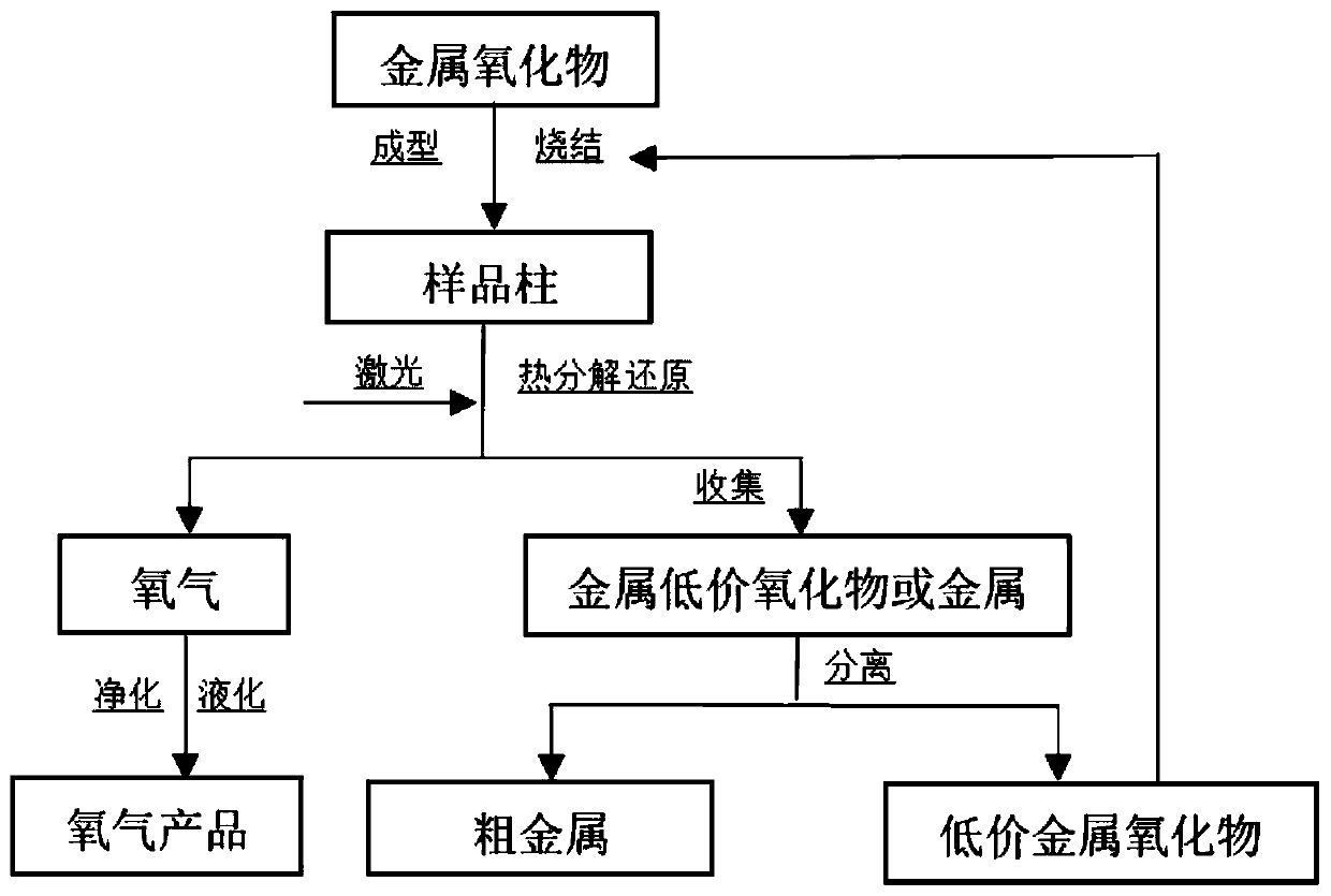
[0043] After mixing the oxide into a certain binder, press molding, sintering, and finally obtain a cylindrical sample with a diameter of 20mm and a length of 20mm;
[0044] Place the sample column in the copper crucible in the vacuum chamber, adjust the sample stage where the copper crucible is placed, so that the selected ablation point on the upper surface of the sample is at the focal point of the laser, and set a water-cooled copper tube 10mm directly above the ablation point of the sample. chip collector.
[0045] In this example, a high-power laser is used, and the laser power can be adjusted between 50-2000W. The laser emits light from directly above the sample. After the laser exits, a focusing lens is used to focus the beam and irradiate the selected area on the upper surface of the sam...
Embodiment 2
[0053] Method is with embodiment 1, and difference is:
[0054] (1) The laser power is 1000W, the radius of the laser ablation point is 0.58mm, and the power density under the corresponding experimental conditions is: 4.06×10 5 W / cm 2 ;
[0055] (2) The amount of defocus is 15 mm overfocus, that is, compared to the situation in which the ablation point on the upper surface of the sample is located at the laser focus position in Example 1 above, in this example, the sample platform is moved downward so that the ablation point on the upper surface of the sample is at 15mm below the laser focus;
[0056] The elemental analysis of the product collected by the water-cooled copper plate collector is carried out, and the elemental analysis of the product is carried out by X-ray energy spectrum analysis (EDS). The local atomic percentage of the collected product is: Ti 66.75%, O 33.25%, and the result shows the oxygen element percentage Reduced to obtain subvalent oxide products. ...
Embodiment 3
[0058] Method is with embodiment 1, and difference is:
[0059] (1) Argon gas with a pressure of 0.2 MPa is passed into the vacuum container, and ablation is carried out with argon gas as the protective atmosphere;
[0060] (2) The degree of vacuum is 3.0×10 -2 Pa;
[0061] The elemental analysis of the product was carried out by EDS. The local atomic percentage of the product collected by the water-cooled copper plate was: Ti94.27%, O2.33%, and the results showed that the percentage of oxygen element decreased.
PUM
 Abstract
Description
Claims
Application Information
 - R&D Engineer
- R&D Manager
- IP Professional
- Industry Leading Data Capabilities
- Powerful AI technology
- Patent DNA Extraction
Browse by: Latest US Patents, China's latest patents, Technical Efficacy Thesaurus, Application Domain, Technology Topic, Popular Technical Reports.
© 2024 PatSnap. All rights reserved.Legal|Privacy policy|Modern Slavery Act Transparency Statement|Sitemap|About US| Contact US: help@patsnap.com