Sintering device and sintering method for optical fiber preform loose body

An optical fiber preform and sintering device technology, which is applied to manufacturing tools, glass manufacturing equipment, glass production, etc., can solve the problems of optical fiber preform structural defects, increase the optical fiber production cycle, and difficult to control the molding process, and reduce the difficulty of deuteration. , Reduce the probability of being oxidized and reduce the effect of bubbles

Inactive Publication Date: 2020-07-17
FENGHUO COMM SCI & TECH CO LTD +1
View PDF5 Cites 4 Cited by
  • Summary
  • Abstract
  • Description
  • Claims
  • Application Information

AI Technical Summary

Problems solved by technology

However, the design of the conventional sintering device cannot meet the requirements of high temperature and negative pressure conditions, and the existing negative pressure sintering adopts a long temperature zone, which means that the entire loose body mother bar is placed in a heating furnace and sintered under negative pressure conditions. The actual forming process Difficult to control and only suitable for sintering of small mandrel master rods
[0006] In addition, some optical fiber preforms have a large number of structural defects in the manufacturing process, resulting in the production of optical fibers that require deuteration for a long time to achieve the purpose of reducing hydrogen sensitivity, increasing the optical fiber production cycle
Patent CN101838114A describes a deuterium gas treatment method for optical fibers, which optimizes the deuterium gas treatment time, but only from the perspective of optical fiber processing, and does not solve this problem from the source of optical fiber preform manufacturing

Method used


Image

  • Sintering device and sintering method for optical fiber preform loose body

Examples


specific Embodiment

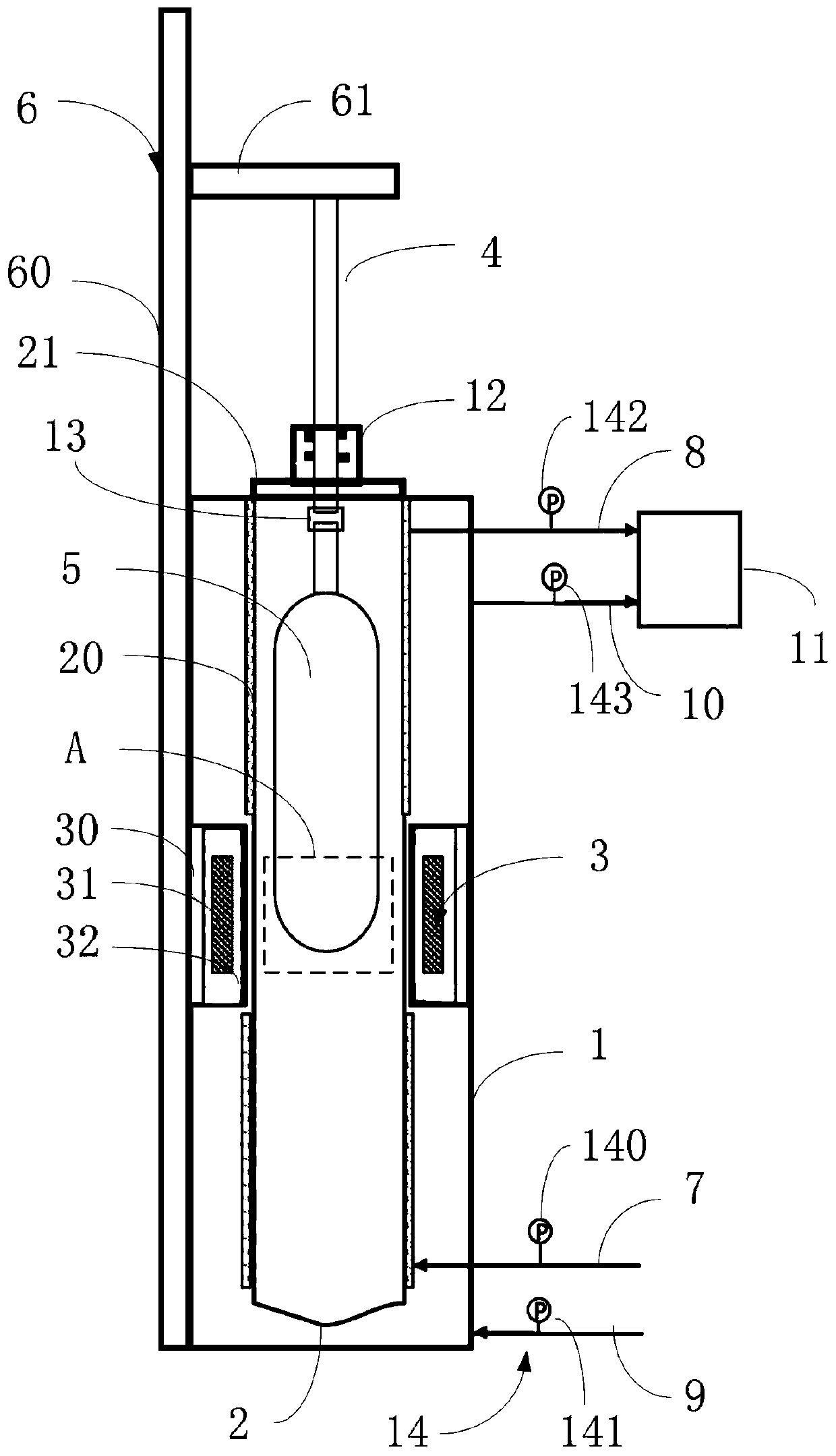
[0085] The density obtained by the OVD outer cladding deposition process is 0.3-0.5g / cm 3 The large-sized preform soot body 5 is placed in the furnace core tube 2, and the bottom of the preform soot body 5 is positioned in the middle of the heating zone as the starting position for dehydroxylation and vitrification sintering. Turn on the vacuum pump to move the furnace core tube 2 Pump the inside and outside to 20mbar to discharge the air in the tube, heat the heating body 31 to 1200°C at a heating rate of 25°C / min, and pass 1slm Cl into the furnace core tube 2 2 , 0.8slm O 2 and 15 slm He, open the rod feeding mechanism 6 to make the preform loose body 5 move downward at a speed of 15mm / min for dehydroxylation, after the top of the preform loose body 5 reaches the heating zone, stop feeding the gas and move the preform loose body 5 Lift to the initial position, turn on the vacuum pump to simultaneously pump the pressure in the furnace core tube 2 and the sintering box 1 to 1...


PUM


Abstract

The invention relates to a sintering device and method for an optical fiber preform loose body. The sintering device comprises a sintering box body, a furnace core pipe, a heating assembly, a guide rod, a rod feeding mechanism, a first pipe set and a second pipe set. The furnace core pipe and the heating assembly are assembled in the sintering box body, and the heating assembly forms a heating area; the guide rod extends into the furnace core pipe and is used for being connected with a preform loose body; the rod feeding mechanism is connected with the guide rod and is used for driving the guide rod to move, so that the preform loose body is heated in the heating area; the first pipe set penetrates through the sintering box body and the wall surface of the furnace core pipe, is communicated with the inner cavity of the furnace core pipe and comprises a first gas inlet pipe and a first gas outlet pipe; the second pipe set penetrates through the wall surface of the sintering box body, iscommunicated with the inner cavity of the sintering box body and comprises a second air inlet pipe and a second air outlet pipe. The invention integrates dehydroxylation, vitrification sintering anddeuterization, can effectively eliminate gas residues in the optical fiber preform, reduces the use amount of He, and eliminates structural defects from the manufacturing source of the optical fiber preform, thereby reducing the hydrogen sensitivity of the optical fiber.

Description

technical field [0001] The present application relates to the field of optical fiber preform preparation, in particular to a sintering device and a sintering method for a loose body of an optical fiber preform. Background technique [0002] External vapor deposition (OVD) and axial vapor deposition (VAD) have become mainstream rod-making technologies in the industry due to their high cost performance. 4 The high-temperature hydrolysis reaction of raw materials and the principle of thermophoresis are used to produce a large-size optical fiber preform loose body, and then a low-water peak, dense and defect-free transparent glass body is obtained through a dehydration-sintering process. [0003] Since the soot body of the optical fiber preform will inevitably contain free water and silicon hydroxyl (Si-OH) during the deposition process, it is necessary to introduce an oxidizing gas such as Cl before vitrification and sintering. 2 and O 2 Carry out high-temperature dehydration...

Claims


Application Information

Patent Timeline
Patent Type & Authority Applications(China)
IPC IPC(8): C03B37/014
CPCC03B37/0146Y02P40/57
Inventor 崔东明孔明伍淑坚
Owner FENGHUO COMM SCI & TECH CO LTD
Why Eureka
Try Eureka