Vertical air extraction sintering machine and sintering process

A sintering machine and ventilation technology, applied in furnaces, charge control, lighting and heating equipment, etc., can solve the problems of large consumption of grate bars, short replacement period, waste of waste heat and energy resources, etc., to improve the preheating effect , reduce the resistance of the material layer and improve the combustion effect

Active Publication Date: 2020-07-17
WUHAN WUTUO TECH
View PDF6 Cites 0 Cited by
  • Summary
  • Abstract
  • Description
  • Claims
  • Application Information

AI Technical Summary

Problems solved by technology

[0008] The air leakage rate of the sintering machine is too large, which not only increases the power consumption, but also reduces the productivity, deteriorates the working environment and causes serious noise
[0009] (2) The amount of sintering flue gas produced is large, and the amount of flue gas (waste gas) generated by sintering ore is 6000m 3 Above, the dust concentration in the flue gas is high, resulting in the difficulty of subsequent dust separation, and the burden of flue gas treatment is heavy
Moreover, there is also a serious (40-60%) problem of air leakage
[0010] (3) The utilization rate of waste heat and waste energy of sintering flue gas produced by the existing belt-type draft sintering machine is low, and the waste heat and waste energy resources are large (currently 1.44GJ waste heat resources are produced per ton of sintering ore, and the recovery rate is less than 50%);
[0011] (4) The existing belt-type draft sintering machine still has large floor space, poor operation stability, large consumption of grate bars, and short replacement period
[0012] The structure of the existing belt-type exhaust sintering machine determines the running direction of materials and flue gas, which will inevitably bring about the occurrence of the above-mentioned problems

Method used


Image

  • Vertical air extraction sintering machine and sintering process
  • Vertical air extraction sintering machine and sintering process
  • Vertical air extraction sintering machine and sintering process

Examples


Embodiment Construction

[0047] Below in conjunction with accompanying drawing, the present invention is further explained as sintering machine:

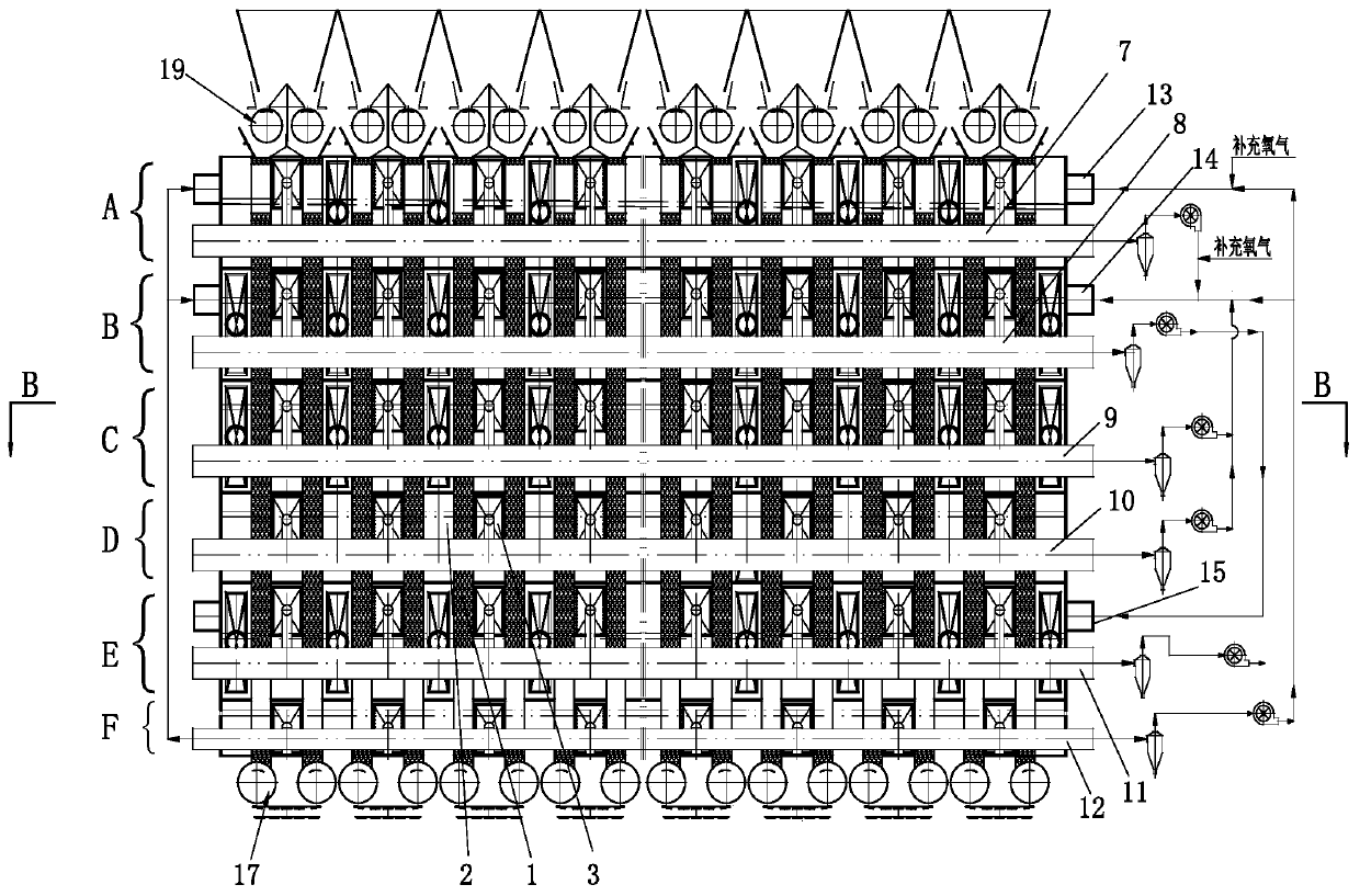
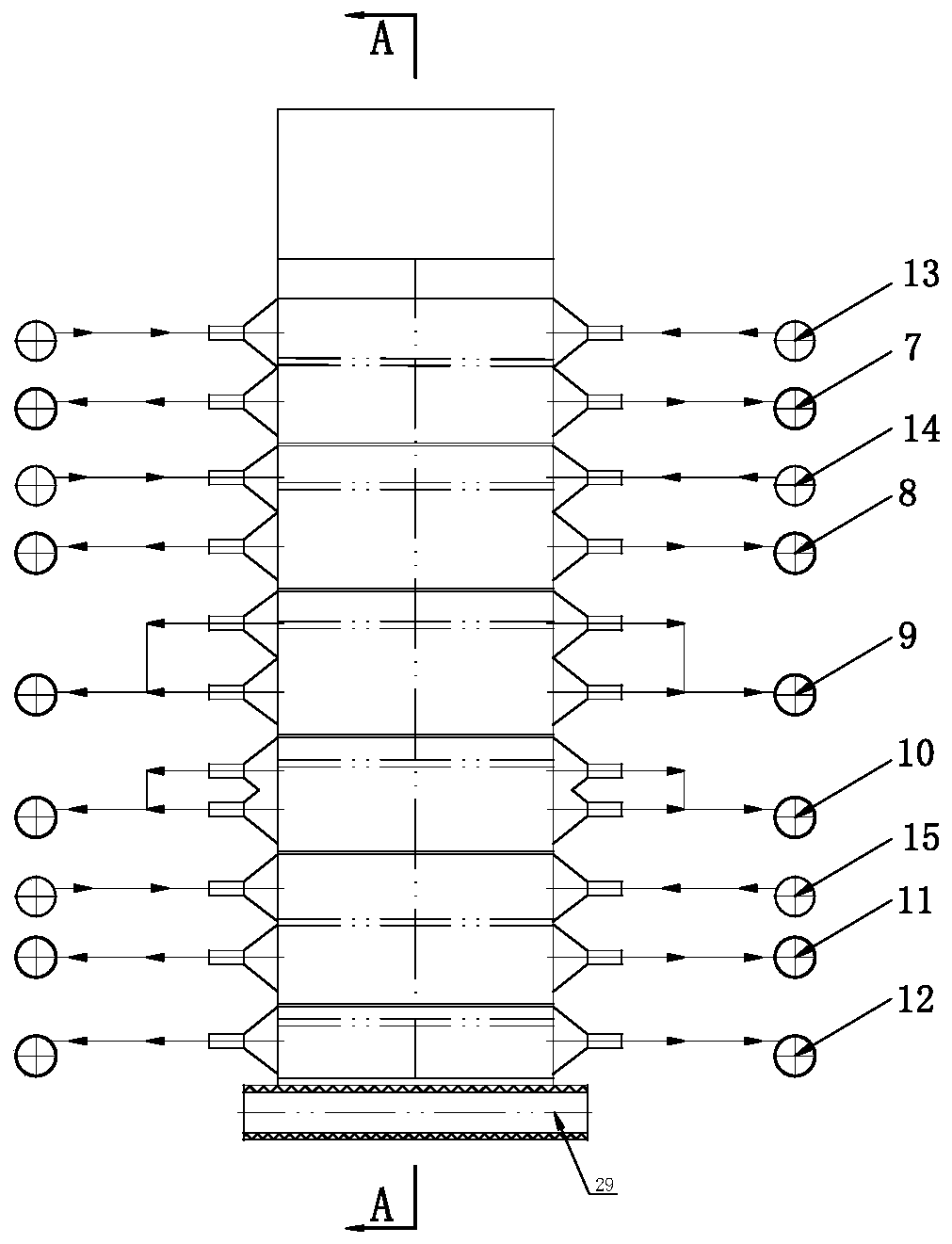
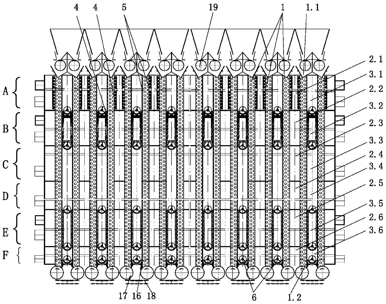
[0048] see figure 1 , figure 2 with image 3 , the vertical draft sintering machine of the present invention comprises at least two sintering chambers 1 arranged at vertical intervals (there are multiple sintering chambers in this embodiment), the sintering chamber 1 is a vertical cuboid shape, and its top is a feed end 1.1 , The bottom is the discharge end 1.2, the front and rear sides of the sintering chamber 1 are baffle plates, the left and right sides are grate bars 5, one side is connected to the air intake channel 2 through the grate bars 5, and the other side is connected to the air outlet through the grate bars 5 The flue 3 is shared between two adjacent sintering chambers 1, and the air inlet passage 2 and / or the gas outlet flue 3 are shared, for example: figure 2 It can be seen from the figure that a certain sintering chamber 1 shares the ai...


PUM


Abstract

The invention discloses a vertical air extraction sintering machine and a sintering process. The sintering machine comprises at least two sintering chambers which are vertically arranged at intervals;the top of each sintering chamber is a feeding end, and the bottom of each sintering chamber is a discharging end; one side of each sintering chamber is communicated with an air inlet channel througha grate bar, and the other side of each sintering chamber is communicated with an air outlet smoke channel through a grate bar; and two adjacent sintering chambers share an air inlet channel and / or an air outlet smoke channel. The sintering process is characterized by adding a sintering mixed material from the feeding end of the top of each sintering chamber, finally obtaining sintered ore and discharging the sintered ore out of the discharging end of the bottom of each sintering chamber. Combustion-supporting gas enters each sintering chamber through the air inlet channel in one side of eachsintering chamber via the grate bar along a horizontal direction; the smoke in each sintering chamber enters the air outlet smoke channel through the grate bar in the other side of each sintering chamber under the negative-pressure action; and two adjacent sintering chambers share an air inlet channel and / or an air outlet smoke channel. The vertical air extraction sintering machine is simple in structure, small in smoke generation amount, free of air leakage, high in stability, small in occupied area and high in waste heat utilization rate; the quality of the sintered ore is improved; the energy is saved; and the consumption is reduced.

Description

technical field [0001] The invention relates to a sintering agglomeration process in the field of iron and steel metallurgy, in particular to a vertical draft sintering machine and a sintering process. Background technique [0002] Sintering is an important link in the iron and steel production process. After mixing raw materials such as iron ore powder, lime and fuel (anthracite, coke powder) uniformly in a certain proportion, the sintered ore with sufficient strength and particle size is formed after sintering. Clinker for ironmaking. [0003] In 1914, J.E.Greenawa lt invented the sintering pan for iron ore powder sintering. With the increasing demand for iron and steel and the expansion of production scale, the draft continuous belt sintering method evolved into the main sintering method. It is almost used in modern large-scale iron and steel enterprises. is the only option. When my country's iron and steel industry was founded in 1926, the sintering machine area was ...

Claims


Application Information

Patent Timeline
IPC IPC(8): F27D17/00F27D19/00F27D3/12F27D7/02F27D15/02
CPCF27D17/004F27D17/008F27D3/12F27D3/123F27D19/00F27D7/02F27D15/0213F27D2003/121F27D2019/0028
Inventor 吴高明
Owner WUHAN WUTUO TECH
Why Eureka
Try Eureka