Rapid separation device and method for protein and starch in wastewater produced during starch processing

A separation device and starch processing technology, applied in chemical instruments and methods, water pollutants, precipitation treatment, etc., can solve the problems of expensive membrane modules, large floor space, and reduced protein quality, and reduce nutrients and COD values. , the cost of capital construction and operation are low, and the effect of improving separation efficiency

Active Publication Date: 2020-08-07
YANTAI UNIV
View PDF5 Cites 0 Cited by
  • Summary
  • Abstract
  • Description
  • Claims
  • Application Information

AI Technical Summary

Problems solved by technology

[0005] There are many factors affecting the foam separation method, and it is usually necessary to add a surfactant to promote protein foaming, while the residual surfactant will affect the later application of the protein; the ultrafiltration method can achieve fractional recovery, high yield, and easy to scale up, but the membrane module Expensive, membrane fouling problem is serious; acid precipitation method makes protein at isoelectric point by adding cheap inorganic acid and tends to aggregate and precipitate, during which protein is partially denatured, and product quality is low; coagulation method is to change the surface of colloidal protein by adding chemical agents characteristics, make the dispersed colloidal particles gather to form large particles and settle (or float), which has strong recovery ability, stable effect, strong hydraulic load resistance, simple process and low operating co

Method used


Image

  • Rapid separation device and method for protein and starch in wastewater produced during starch processing

Examples


Example Embodiment

[0054] Example 1

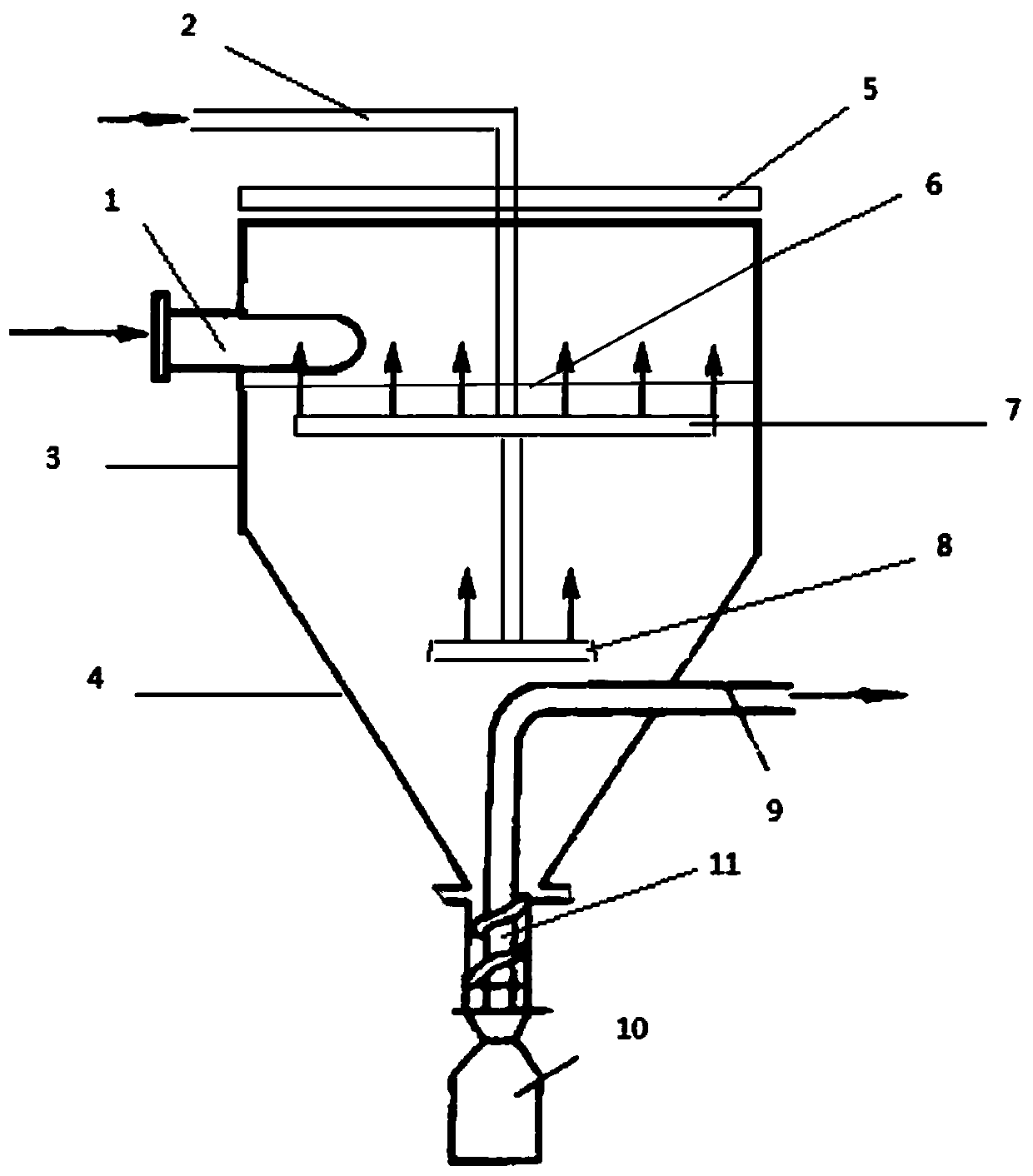
[0055] The rapid separation device for protein and starch in the wastewater from starch processing includes a separation device body (stainless steel material), a starch collection device 10, a frothing device, a frothing device and a skimming device.

[0056] The separation device body includes a cylindrical section 3 and an inverted cone section 4.

[0057] The cylinder section 3 has a height of 3m, a diameter of 1.5m, and an open top. A feed port 1 is set on the side wall 0.70m from the top; the feed port 1 is arranged tangentially to the inner wall of the cylinder section 3.

[0058] The angle between the bus bar of the inverted cone section 4 and the top surface is 60 ° , The top end of the inverted cone section 4 and the bottom end of the cylindrical section 3 are integrally formed, and the bottom end of the inverted cone section 4 is connected to the starch collecting device 10.

[0059] A liquid discharge pipe 9 is provided in the inverted cone section 4;

[...

Example Embodiment

[0068] Example 2

[0069] The processing time of sweet potato starch is short, and the daily output is large. The device of Example 1 can quickly treat the waste water generated during the processing of sweet potato starch.

[0070] Make sweet potato starch extract wastewater to 10m 3 / h into the liquid ejector, the gas is brought in and evenly distributed in the sweet potato starch extraction wastewater, forming a relatively stable protein foam.

[0071] The foam-containing waste liquid is pumped into the separation device body along the tangential direction at a linear speed of 5m / s. Air is passed through the vent pipe 2. When the filling liquid level reaches 0.2m below the inlet, the liquid discharge pipe 9 is opened.

[0072] The foam skimming device 5 is used to remove the foam, and the protein product is obtained after demulsification after collection.

[0073] The starch settles into the starch collecting device 10.

[0074] The waste water after separating starch and protein fl...

Example Embodiment

[0076] Example 3

[0077] The device of Example 1 was used to treat wastewater from the pea starch processing process.

[0078] In the pea starch extraction wastewater, 10% (volume ratio) is injected with 0.05MPa compressed air to form a more stable protein foam.

[0079] The foam-containing wastewater is pumped into the separation device body along the tangential direction at a linear speed of 8m / s. Air is passed through the vent pipe 2. When the filling liquid level reaches 0.4m below the inlet, the liquid discharge pipe 9 is opened.

[0080] The foam skimming device 5 is used to remove the foam, and the protein product is obtained after demulsification after collection.

[0081] The starch settles into the starch collecting device 10.

[0082] The waste water after separating starch and protein flows out through the liquid discharge pipe 9.

[0083] The initial COD of the treated wastewater is about 15000mg / L, after treatment, the COD drops to about 5500mg / L, and the COD removal rate...


PUM


Abstract

The invention discloses a rapid separation device for protein and starch in wastewater produced during starch processing. The rapid separation device comprises a separation device body, a starch collecting device, a foaming device and a skimming device, wherein the separation device body comprises a cylinder section and an inverted cone section; the top end of the cylindrical section is open, anda feed port is formed in the side wall of the cylindrical section; the feeding port is tangentially formed relative to the inner wall of the cylindrical section; the inverted cone section is connectedto the bottom end of the cylindrical section and is provided with a liquid discharge pipe; the starch collecting device communicates with the bottom end of the inverted cone section; the foaming device is mounted in the separation device body; and the skimming device is arranged at the top of the separation device body. The invention also discloses a corresponding separation method. According tothe device and the method in the invention, protein and starch can be separated from the wastewater produced during starch processing at the same time, low-cost resource utilization of the wastewaterproduced during starch processing is achieved, and the requirement for large daily treatment capacity of the wastewater produced during starch processing can be met; and operation is simple and rapid,conditions are mild, complex equipment is not needed, and high-quality starch and protein can be obtained.

Description

technical field [0001] The invention relates to the technical field of production waste recycling, and more specifically relates to a device and a method for rapidly separating protein and starch in waste water in a starch processing process. Background technique [0002] The processing of sweet potato, cereal and bean starch consumes a lot of water, resulting in a large amount of wastewater discharge, and the wastewater is a high-concentration acidic organic wastewater, which is one of the most polluted wastewater in the food industry. At present, the anaerobic-aerobic combined biological treatment method is generally used to treat starch processing wastewater at home and abroad. Other treatment technologies include electrocoagulation, electrochemical method, Fenton-anaerobic method, etc., but these technologies are faced with high investment costs, The problem of high operating costs. Therefore, how to recycle wastewater from starch processing and reduce treatment costs h...

Claims


Application Information

Patent Timeline
IPC IPC(8): C02F9/02C02F101/34C02F101/38
CPCC02F1/24C02F2001/007C02F2101/38C02F2101/34Y02W10/10
Inventor 姜爱莉单守水于贞刘恒旭
Owner YANTAI UNIV
Why Eureka
Try Eureka