High-efficiency three-dimensional mixing plant

A three-dimensional, mixing plant technology, applied in the direction of dust removal, loading/unloading, and selling raw material supply devices, etc., can solve the problems of low work efficiency, large floor area, and poor safety control, and achieve optimal layout, The effect of reducing the footprint

Inactive Publication Date: 2020-08-28
山东润山机械有限公司
View PDF9 Cites 0 Cited by
  • Summary
  • Abstract
  • Description
  • Claims
  • Application Information

AI Technical Summary

Problems solved by technology

At present, the existing factories for processing construction waste have the following disadvantages: large area; too many operators, difficult to control safety; low overall work efficiency;

Method used


Image

  • High-efficiency three-dimensional mixing plant
  • High-efficiency three-dimensional mixing plant
  • High-efficiency three-dimensional mixing plant

Examples


Embodiment 1

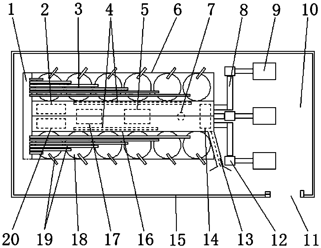
[0029] Such as figure 1 A high-efficiency three-dimensional mixing plant shown includes a production and processing area 6 and three product concentration stations 9 located on the same side of the production and processing area 6. From top to bottom, they are an asphalt station, a water stabilization station and a commercial station. Concrete station, the production and processing area 6 includes a row of raw material bins 3 and a row of recycled material bins 18 oppositely arranged, and the crushing workshop 1 located on the side of the raw material bins 3 and recycled material bins 18 facing away from the product concentration station 9 , and the double-layer factory building 16 of steel structure that is located between the original material bin 3 and the recycled material bin 18, and there is a one-to-one corresponding lifting between the crushing workshop 1 and each original material bin 3 and each recycled material bin 18 The machine 19 is used to transport the material...

Embodiment 2

[0036] The difference between this embodiment and embodiment 1 is:

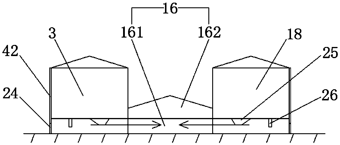
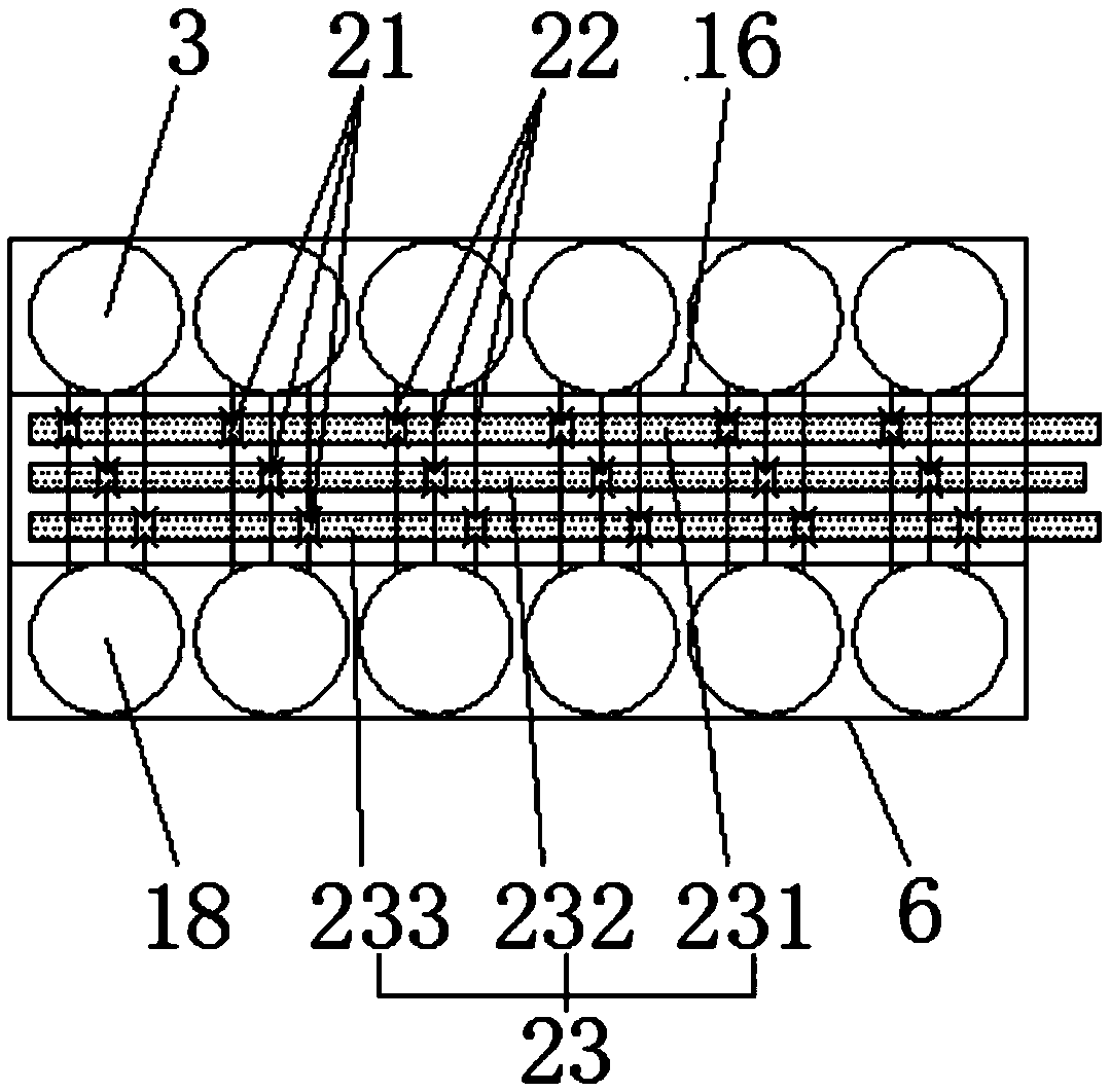
[0037] In this example, if figure 2 , Figure 4 and Image 6 As shown, the lower end of each of the silos 27 faces away from the side of the double-storey factory building 16 and is provided with two loading and unloading openings 26, and the loading and unloading openings 26 are connected with a dust collector 37 and a telescopic barrel 38 , the loading and unloading port 26 is provided with a loading hydraulic valve 36, and the ground directly below the loading and unloading port 26 is provided with a weighbridge 33, and the loading hydraulic valve 36 and the weighbridge 33 are respectively connected with the control electrical connection; the bottom of each of the silos 27 is supported on the ground by fourteen round silo legs 35; the outer sides of the original silos 3 and the regenerated silos 18 are provided with dust-proof walls extending to the ground. Housing 42, and dust-proof housing 42 is prov...


PUM

PropertyMeasurementUnit
lengthaaaaaaaaaa
heightaaaaaaaaaa
widthaaaaaaaaaa

Abstract

The invention discloses a high-efficiency three-dimensional mixing plant, and belongs to the field of building material preparation. The high-efficiency three-dimensional mixing plant comprises a rowof original stock bins and a row of recycled stock bins which are oppositely arranged, a crushing workshop with lifting machines is arranged on the same side of the original stock bins and the recycled stock bins, a belt conveyor workshop and a production office area located above the belt conveyor workshop are arranged between the original stock bins and the recycled stock bins, parallel multipleproportioning belts are arranged in the belt conveyor workshop, the original stock bins and the recycled stock bins are arranged parallel to the length direction of the proportioning belts, and a feeding belt is arranged between each stock bin and each proportioning belt; the lower end of each stock bin is provided with at least two sets of feeding and discharging ports, each feeding and discharging port is provided with a gate valve, and each feeding belt is provided with a belt scale; the gate valves and the belt scales are electrically connected with a controller in the production office area; and a shell of the belt conveyor workshop is provided with through openings allowing the corresponding belts to pass through, and a sealing dust cover is arranged above the feeding belts. According to the high-efficiency three-dimensional mixing plant, the occupied area is small, and the land can be saved; the automation degree is high, and the operation cost can be saved; and the high-efficiency three-dimensional mixing plant is environment-friendly and reaches the standard.

Description

technical field [0001] The invention relates to the field of building material preparation, in particular to a high-efficiency three-dimensional mixing plant. Background technique [0002] With the rapid development of my country's economic construction and most of the expansion of urban construction, human beings use a large number of artificial building materials clay, pebbles, sand, limestone, iron ore powder, etc., resulting in excessive development of mineral resources, large consumption of energy and pollution of the environment and The conflicts between phenomena such as destruction of ecology and the earth's resources, the limited capacity of the earth's environment, and the safety of the earth's ecosystem are becoming increasingly acute. There is an urgent need to develop and use sustainable renewable building materials to alleviate and eliminate construction waste ( The solid construction waste generated by demolition in the city) poses a serious threat to the living...

Claims


Application Information

Patent Timeline
Patent Type & Authority Applications(China)
IPC IPC(8): B65G37/00B65G69/18B65G65/32B65G67/04B65G15/32B02C23/00B08B15/04B28C7/06
CPCB02C23/00B08B15/04B28C7/06B65G15/32B65G37/00B65G65/32B65G67/04B65G69/182
Inventor 杨山峰
Owner 山东润山机械有限公司
Why Eureka
Try Eureka