A Nanoparticle-Driven Method for Low-Energy Ultrasonic Metal Welding

A nanoparticle and metal welding technology, applied in welding equipment, metal processing equipment, non-electric welding equipment, etc., can solve the problems of unfavorable application due to surface damage, reduce welding input energy, and limit application prospects, so as to achieve easy control of welding quality, Reduced risk, flexible and simple operation

Active Publication Date: 2022-06-28
HARBIN INSTITUTE OF TECHNOLOGY SHENZHEN (INSTITUTE OF SCIENCE AND TECHNOLOGY INNOVATION HARBIN INSTITUTE OF TECHNOLOGY SHENZHEN)
View PDF0 Cites 0 Cited by
  • Summary
  • Abstract
  • Description
  • Claims
  • Application Information

AI Technical Summary

Problems solved by technology

In addition, the encapsulation of heat dissipation chambers in electronic devices usually adopts epoxy resin bonding, resistance welding or electron beam welding. Application of the above-mentioned welding method in the package of heat dissipation cavity of electronic device
[0003] Traditional ultrasonic welding of metals mainly improves joint reliability and achieves good connections by adjusting input energy, amplitude, time, and ultrasonic power. However, when the thickness of the conductive layer to be welded exceeds the weldable limit of ultrasonic equipment, adjusting the process window to improve welding quality will No longer effective, and the surface damage caused by excessive energy input is not conducive to the application of ultrasonic metal welding methods in small thermally sealed cavities
At present, relevant research has pointed out that the method of intermediate layer can be used to increase the metallurgical speed and strengthen the weld. For example, D.L. Chen's team used Zn intermediate layer to improve the strength of Al-Cu joints, but this method is not suitable for reducing welding input energy, which limits its use. Prospects for future applications

Method used


Image

  • A Nanoparticle-Driven Method for Low-Energy Ultrasonic Metal Welding
  • A Nanoparticle-Driven Method for Low-Energy Ultrasonic Metal Welding
  • A Nanoparticle-Driven Method for Low-Energy Ultrasonic Metal Welding

Examples


Embodiment 1

[0037] A kind of nano copper paste, it adopts the following steps to prepare:

[0038] 1. Take by weighing 10 g of copper sulfate pentahydrate powder and join in 40 ml of ethylene glycol, and be heated to 75° C., obtain solution A after the copper sulfate pentahydrate powder is completely dissolved.

[0039] II. Weigh 16 g of sodium hypophosphite powder and 10 g of polyvinylpyrrolidone into 160 ml of ethylene glycol, and heat to 75° C. After the powder is completely dissolved, solution B is obtained.

[0040] III. Slowly adding solution A into solution B, heating to 75° C. and reacting for 1.5 h to prepare dispersion liquid C containing copper nanoparticles.

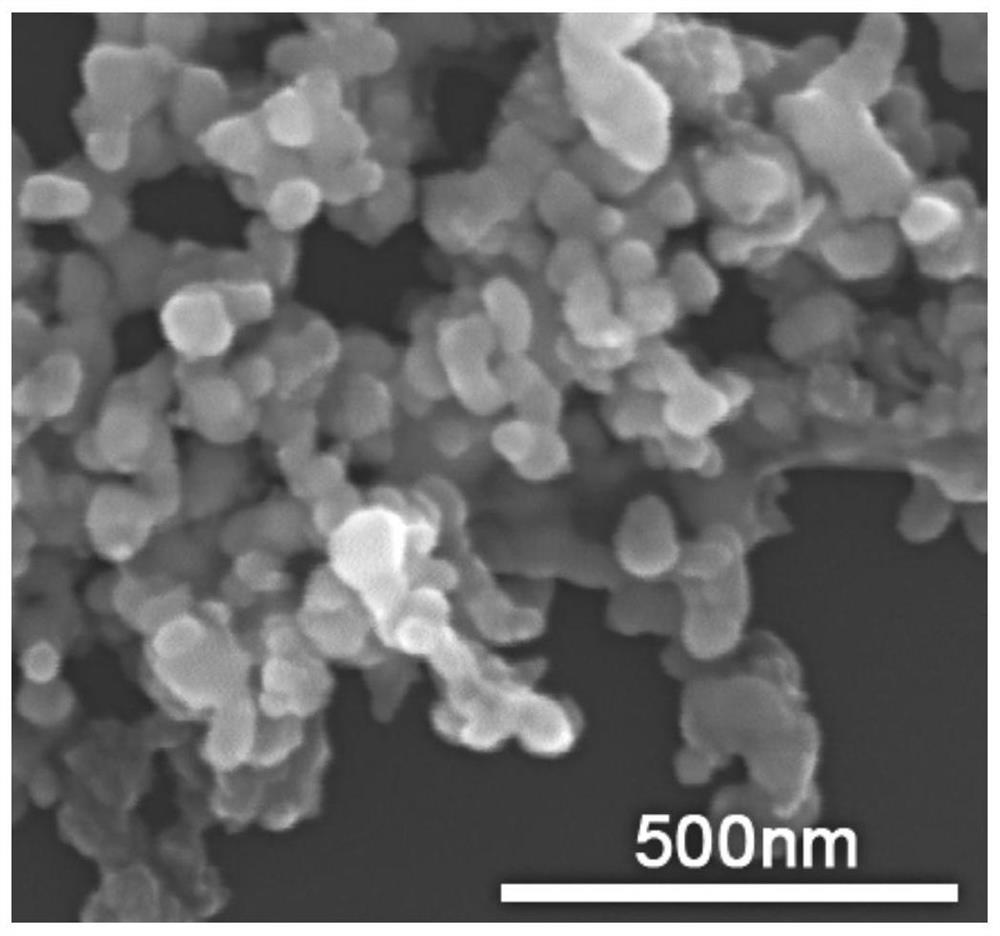
[0041] IV. After the dispersion liquid C is cooled to room temperature, centrifugation is performed to separate the copper nanoparticles and the organic solvent. The separated copper nanoparticles were washed 2-4 times with a mixed solution D of deionized water and absolute ethanol in ultrasonic vibration. The size of ...

Embodiment 2

[0045] Ultrasonic welding of copper-copper metal and interface characterization using nano-copper paste intermediate layer

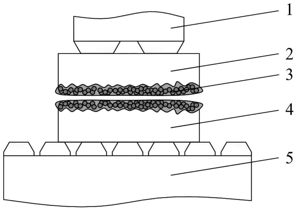
[0046] like figure 2As shown, using the nano-copper paste of Example 1 to ultrasonically weld copper-copper metal, including the following steps:

[0047] 1. The upper layer of material to be welded 2 and the lower layer of material to be welded 4 are both 20 mm × 10 mm × 0.5 mm copper strips, and the connection surface of the material to be welded 2 and the material to be welded 4 is polished with 800# sandpaper to remove the surface oxide layer, and then Immerse in absolute ethanol for ultrasonic cleaning for 3 min.

[0048] II. Select the interlayer nano-particle paste as nano-copper paste, screen-print the copper nano-particle paste with a thickness of 10 μm on the surfaces of the material to be welded 2 and the material to be welded 4, and use figure 2 Place the upper and lower layers of copper strips to be soldered in the manner shown.

[0049...

Embodiment 3

[0056] Example 3 Ultrasonic welding of aluminum-copper metal using nano-copper paste intermediate layer

[0057] A method for ultrasonically welding aluminum-copper metal using copper nanoparticles, comprising the following steps:

[0058] I. The material to be welded on the upper layer is aluminum strip, and the material to be welded on the lower layer is copper strip, both of which are 20 mm×10 mm×0.5 mm in size. The connection surface of the material to be welded and the material to be welded is polished with 800# sandpaper to remove the surface oxide layer , and then immersed in absolute ethanol for ultrasonic cleaning for 3 min.

[0059] II. Select the interlayer nano-particle paste as nano-copper paste, screen-print nano-copper paste with a thickness of 10 μm on the surface of the material to be welded and the material to be welded, and use such as figure 2 Place the upper and lower layers of copper strips to be soldered in the manner shown.

[0060] III. According to...


PUM

PropertyMeasurementUnit
diameteraaaaaaaaaa
thicknessaaaaaaaaaa
sizeaaaaaaaaaa

Abstract

The invention provides a method for nanoparticle-driven low-energy ultrasonic metal welding, which includes: preparing nanoparticle paste or powder; coating the surface to be welded with 1-50 μm thick nanoparticle paste or powder on the upper and lower layers of the metal to be welded, Ultrasonic welding is then performed at room temperature or under heating. Adopting the technical scheme of the present invention, the traditional solid-phase connection at the peak of the rough surface in the ultrasonic welding process, as well as the size effect, frictional heating effect and gap filling effect of the nano-particles in the gap are integrated, thereby realizing lower ultrasonic welding input energy Form a good ultrasonic welded joint, simplify the production process, reduce the impact of the material to be welded, and improve the sealing performance of the weld seam, the mechanical properties of the welded joint, and the electrical and thermal conductivity.

Description

technical field [0001] The invention belongs to the technical field of welding, and in particular relates to a method for nanoparticle-driven low-energy ultrasonic metal welding. Background technique [0002] In recent years, as the pressure of resource supply and environmental pollution continues to increase, the use of fossil fuels such as gasoline and diesel has been reduced, and the gradual use of lithium-ion batteries as power energy has become the main development direction of the future automotive field. The manufacture of lithium batteries for vehicles includes processes such as pulping, coating, welding, assembly and chemical formation, in which the connection of the pole pieces and the packaging of the battery need to be welded. At the same time, the increase in the capacity and power requirements of lithium batteries will also bring about a surge in the number of series-parallel battery modules. On the premise of ensuring the reliability of the joints, reducing th...

Claims


Application Information

Patent Timeline
Patent Type & Authority Patents(China)
IPC IPC(8): B23K20/10B23K20/16B23K20/24B23K20/26
CPCB23K20/10B23K20/16B23K20/24B23K20/26
Inventor 计红军马秋晨宋成李明雨
Owner HARBIN INSTITUTE OF TECHNOLOGY SHENZHEN (INSTITUTE OF SCIENCE AND TECHNOLOGY INNOVATION HARBIN INSTITUTE OF TECHNOLOGY SHENZHEN)
Why Eureka
Try Eureka