Transmission electron microscope high-resolution in-situ suspension type temperature difference pressurization chip and preparation method thereof

A transmission electron microscope, high-resolution technology, used in material analysis using radiation, material analysis using wave/particle radiation, circuits, etc. The effect of temperature difference and pressure function, convenient sample placement, and low sample drift rate

Pending Publication Date: 2020-12-25
XIAMEN UNIV
View PDF0 Cites 1 Cited by
  • Summary
  • Abstract
  • Description
  • Claims
  • Application Information

AI Technical Summary

Problems solved by technology

[0003] The current temperature difference chip still has defects such as low heating and cooling rate, insufficient accuracy of temperature measurement and temperature control, low resolution, high sample drift rate, inability to realize temperature difference and pressurization functions at the same time, and inconvenient sample placement. Some temperature difference chips are improved

Method used


Image

  • Transmission electron microscope high-resolution in-situ suspension type temperature difference pressurization chip and preparation method thereof
  • Transmission electron microscope high-resolution in-situ suspension type temperature difference pressurization chip and preparation method thereof
  • Transmission electron microscope high-resolution in-situ suspension type temperature difference pressurization chip and preparation method thereof

Examples


Embodiment 1

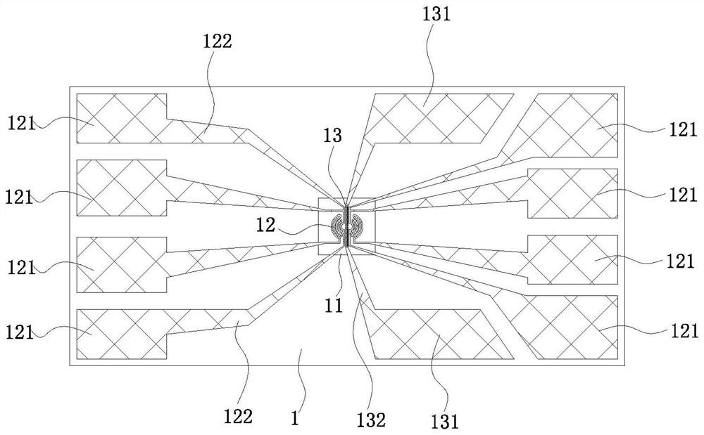
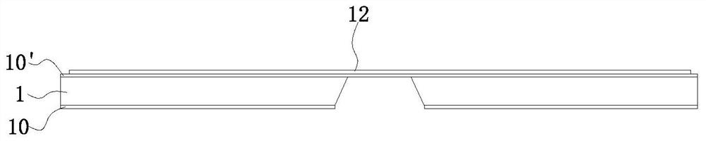
[0031] like Figure 1-Figure 3 As shown, this embodiment provides a TEM high-resolution in-situ suspended temperature difference pressurized chip, which includes a substrate 1 covered with an insulating layer 10 on the front and back of the substrate 1 . Wherein, the substrate in this embodiment is a silicon substrate, and the insulating layer is a silicon nitride or silicon oxide insulating layer.

[0032] There is a central window 11 in the middle of the substrate 1, the central window 11 is suspended, and the central window 11 is covered with a support layer 10', the support layer 10' is a silicon nitride layer or a silicon oxide layer.

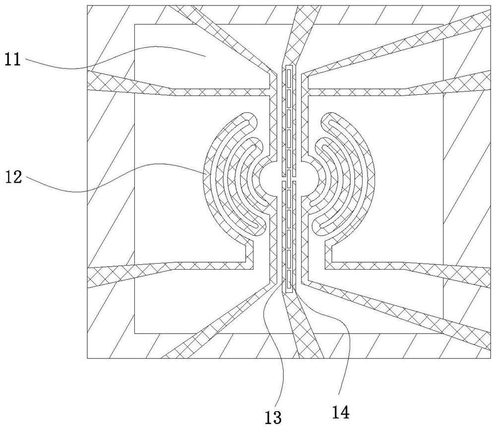
[0033] The supporting layer in the central window 11 has two symmetrical heating wires 12 and two pressure circuits 13 symmetrically arranged up and down, and the two pressure circuits 13 are located in the gap between the two heating wires 12 .

[0034] Wherein, the heating wire 12 is a spiral circular arc heating wire, there is a gap be...

Embodiment 2

[0045]This embodiment provides a method for preparing a high-resolution transmission electron microscope in-situ suspended temperature difference pressurized chip, which includes the following steps:

[0046] S1. Prepare a Si(100) wafer A with silicon nitride or silicon oxide layers on both sides, the thickness of the silicon nitride or silicon oxide layer is 0.5-5um, and the thickness of the silicon wafer is 50-500um;

[0047] S2. Using the photolithography process, transfer the central window pattern from the photolithography mask to any side of the above-mentioned wafer A, use this as the back side, and then develop it in a positive photoresist developer to obtain wafer A-1;

[0048] Preferably, the photolithography process is exposed under the hard contact mode of the ultraviolet lithography machine; the photoresist used in the photolithography process is AZ5214E; the developing time is 65s;

[0049] More preferably, the exposure time is 20s;

[0050] S3. Using reactive i...


PUM

PropertyMeasurementUnit
thicknessaaaaaaaaaa

Abstract

The invention relates to a transmission electron microscope high-resolution in-situ suspension type temperature difference pressurization chip and a preparation method thereof. The chip comprises a substrate of which two sides are covered with insulating layers, a central window is arranged in the middle part of the substrate, the central window is suspended, the central window is also covered with a support layer, two heating wires which are symmetrically arranged left and right and two pressurizing circuits which are symmetrically arranged up and down are arranged on the supporting layer inthe central window, the two pressurizing circuits are positioned in a gap between the two heating wires, the heating wires are connected with four heating electrodes, the heating electrodes are connected to different positions of the heating wires through heating lines, the pressurizing circuits are connected with pressurization electrodes, the pressurization electrodes are connected with the corresponding pressurizing circuits through pressurizing lines. The chip can achieve the temperature difference function and the pressurization function at the same time.

Description

technical field [0001] The invention relates to the field of in-situ characterization, in particular to a transmission electron microscope high-resolution in-situ suspended temperature difference pressure chip and a preparation method thereof. Background technique [0002] In situ transmission electron microscopy is widely used in various scientific fields due to its advantages of ultra-high spatial resolution (atomic level) and ultra-fast time resolution (millisecond level), which provides researchers with the opportunity to explore the microstructure of new materials. New ideas and research methods. The main performance is to build a visual window in the electron microscope, introduce external field effects such as thermal field, light field, electrochemical field, etc., and perform real-time dynamic in-situ testing on the sample. Researchers can use in-situ testing technology to capture the dynamic response of samples to the environment, including important information s...

Claims


Application Information

Patent Timeline
Patent Type & Authority Applications(China)
IPC IPC(8): G01N23/02G01N23/20033H01J37/20H01J37/26
CPCG01N23/02G01N23/20033H01J37/20H01J37/261
Inventor 廖洪钢何娜娜江友红
Owner XIAMEN UNIV
Why Eureka
Try Eureka