
Lithium ion battery repeating unit, lithium ion battery, using method of lithium ion battery, battery module and automobile

A lithium-ion battery, repeating unit technology, applied in secondary battery charging/discharging, battery electrodes, non-aqueous electrolyte battery electrodes, etc., can solve the problems of low battery energy density, safe battery safety, etc. Reduce battery self-discharge, good high temperature performance

Active Publication Date: 2021-01-12
BYD CO LTD
View PDF14 Cites 0 Cited by
  • Summary
  • Abstract
  • Description
  • Claims
  • Application Information

AI Technical Summary

Problems solved by technology

[0006] The purpose of the present disclosure is to provide a lithium-ion battery repeating unit, a lithium-ion battery and its use method, a battery module, and a car, so as to solve the problems of low energy density of batteries in the prior art, safety problems caused by lithium dendrites, and battery Safety issues, self-discharge issues, and electrolyte consumption issues in high-temperature environments, while reducing the complexity of battery preparation, reducing costs, and further enhancing battery performance

Method used


Image

  • Lithium ion battery repeating unit, lithium ion battery, using method of lithium ion battery, battery module and automobile
  • Lithium ion battery repeating unit, lithium ion battery, using method of lithium ion battery, battery module and automobile
  • Lithium ion battery repeating unit, lithium ion battery, using method of lithium ion battery, battery module and automobile

Examples


Embodiment approach

[0082] In a specific embodiment, the metal body with surface pores may have micropores. For example, in one embodiment, the metal body with surface pores may have two main surfaces perpendicular to the stacking direction, wherein at least one of the main surfaces may be Micropores are formed. Among them, micropores of a certain depth can be formed on the non-porous base metal by methods such as in-situ generation, chemical and physical deposition, and corrosion formation, so as to obtain a metal body with surface pores. For example, use micron copper or copper alloy foil, and use physical vapor deposition (PVD) or chemical vapor deposition (CVD) to deposit a certain thickness of porous metal copper or carbon on the two sides of the foil; or, micron copper or copper The alloy foil is placed in an acidic or alkaline chemical corrosion solution and corroded for a certain period of time to form corrosion holes on both sides.

[0083] In another preferred embodiment, refer to Fi...

Embodiment 1

[0108] 1. Preparation of positive electrode: Weigh the positive active material (LiCoO 2 ) 1kg, conductive agent carbon nanotube 20g and binding agent polyvinylidene fluoride (PVDF) 20g join in the N-methylpyrrolidone of 1kg, then stir 30min in the stirrer, form stable and uniform slurry; The slurry Coat evenly on aluminum foil, transfer to an oven to dry at 80°C; press the dried pole pieces under 2MPa pressure, cut them into 50mm×75mm pole pieces, and spot-weld the positive lugs, surface density 30mg / cm 2 .

[0109] 2. Preparation of the separator: take a common commercial 11 μm PVDF-coated lithium battery PE separator and cut it into 77 mm wide.

[0110]3. Preparation of the first negative electrode: Weigh 100g of nano-silica powder as an inorganic porous conductive material, 10g of PVDF binder, dissolve in 150g of N-methylpyrrolidone, and then stir in a mixer for 50min to form a stable and uniform Slurry: The slurry is uniformly coated on a copper mesh (conductor layer) ...

Embodiment 2

[0115] 1. Prepare the positive electrode and separator according to the method in Example 1.

[0116] 2. Prepare the first negative electrode: select a copper mesh (conductor layer) with a thickness of 15 μm, and use magnetron sputtering equipment to sputter ZrO on one side 2 For the material, the sputtering time is 5 minutes, the thickness is 1.5 μm, the porosity of the copper mesh is 60%, and the hole diameter is 1 mm. Weigh 1 kg of negative electrode active material (D50 of 2 μm silicon oxide and carbon nanotube composite negative electrode material), 10 g of conductive agent acetylene black, 30 g of binder styrene-butadiene rubber (SBR) and 20 g of sodium carboxymethyl cellulose (CMC) Add it to 1kg of deionized water, and then stir in a mixer to form a stable and uniform slurry; coat the slurry evenly on the surface of the above-mentioned conductor layer, and then transfer it to an oven for drying at 80°C; After the pole piece is pressed under 2MPa pressure, it is cut int...


PUM

PropertyMeasurementUnit
thicknessaaaaaaaaaa
thicknessaaaaaaaaaa
thicknessaaaaaaaaaa

Abstract

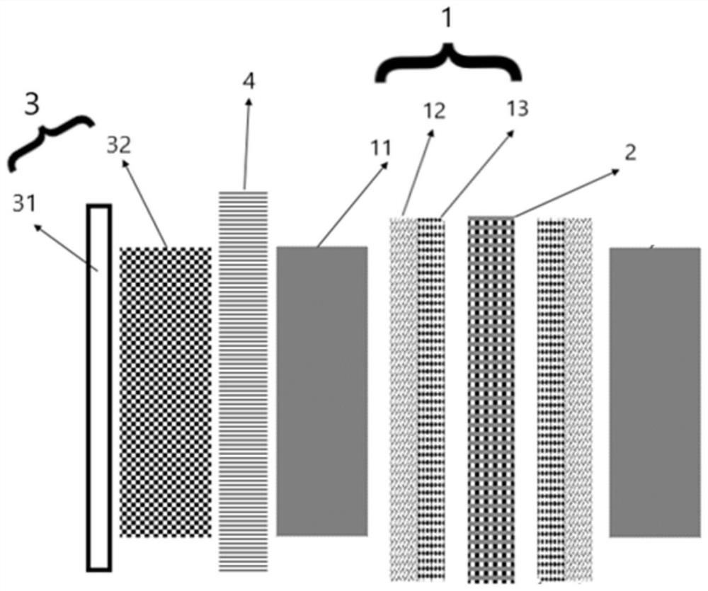
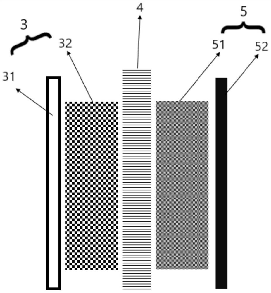
The invention relates to a lithium ion battery repeating unit, a lithium ion battery, a use method of the lithium ion battery, a battery module and an automobile. The repeating unit comprises a positive electrode, a first diaphragm and a negative electrode which are sequentially stacked in the stacking direction, and the negative electrode comprises a first negative electrode and a second negativeelectrode which are not electrically contacted with each other during charging; wherein the first negative electrode comprises an active material layer, a conductor layer and an insulating layer, theconductor layer contains an inorganic porous conductive material, and the insulating layer contains an inorganic compound; and in the negative electrode, the active material layer, the conductor layer, the insulating layer, the second negative electrode, the insulating layer, the conductor layer and the active material layer are sequentially stacked according to the stacking direction, and the second negative electrode is coated with an insulating material. The lithium ion battery disclosed by the invention is relatively high in energy density, and the safety problem caused by lithium dendrites in an existing battery can be solved.

Description

technical field [0001] The present disclosure relates to the battery field, in particular, to a lithium-ion battery repeating unit, a lithium-ion battery and a method for using the same, a battery module and an automobile. Background technique [0002] At present, there are generally two types of batteries used in the market: one is an energy conversion device represented by a fuel flow battery or a liquid flow battery that separates the energy storage active material from the stack that provides a chemical reaction site; the other is a positive electrode, The diaphragm and the negative electrode are uniformly laminated or wound, and the active material is distributed on the positive electrode and the negative electrode to form an energy conversion device that stores energy and power as a whole. The lithium-ion battery belongs to the typical second type, and its positive electrode, separator, and negative electrode are evenly arranged in opposite directions. The positive el...

Claims


Application Information

Patent Timeline
Patent Type & Authority Applications(China)
IPC IPC(8): H01M10/0585H01M10/0525H01M4/13H01M4/62H01M10/44
CPCH01M10/0585H01M10/0525H01M4/13H01M4/628H01M10/446H01M2220/20H01M2004/027Y02E60/10Y02P70/50
Inventor 王蒙李世彩周青甘永青焦晓朋
Owner BYD CO LTD
Learn More