Desulfurization wastewater zero discharge system for gradient utilization of flue gas waste heat and working method thereof

A technology for desulfurization wastewater and flue gas waste heat, which is applied in the treatment of gaseous effluent wastewater, chemical instruments and methods, heating water/sewage treatment, etc., and can solve the problems of high operating costs, high operating pressure of reverse osmosis membranes, and unsatisfactory operating effects, etc. problems, to achieve the effect of increasing heat exchange area, improving heat utilization efficiency, and good application prospects

CN112239242AActive Publication Date: 2021-01-19HUANENG CLEAN ENERGY RES INST
9 Cites 2 Cited by

Patent Information

Authority / Receiving Office
CN · China
Patent Type
Applications(China)
Current Assignee / Owner
Publication Date
2021-01-19

Smart Images

  • Figure 1
    Figure 1
Patent Text Reader

Abstract

The invention discloses a desulfurization wastewater zero discharge system for gradient utilization of flue gas waste heat and a working method of the desulfurization wastewater zero discharge system,and belongs to the technical field of desulfurization wastewater treatment. The system comprises a first air inlet device, a second air inlet device, a first air heat exchanger, a second air heat exchanger, a first flue gas heat exchanger, a second flue gas heat exchanger, a spray drying tower, a dust remover, an evaporation concentration tower and a desulfurization wastewater pool. High-temperature flue gas at the tail of a boiler is used for increasing the air temperature, desulfurization wastewater is evaporated and dried by high-temperature air through gradient utilization of the temperature, the cooled air is used for concentrating and reducing the desulfurization wastewater, the dust remover is used for recovering dried salt in the wastewater, and the air heat exchanger is used forrecovering heat in air at an outlet of a system for preheating the air. Compared with a conventional desulfurization waste water zero-discharge method, waste heat in flue gas is fully utilized, concentration and drying of waste water are synchronously achieved, the influence on water balance and material balance of gas in an original flue is small, and good application prospects are achieved.
Need to check novelty before this filing date? Find Prior Art

Description

technical field

[0001] The invention belongs to the technical field of desulfurization wastewater treatment, and in particular relates to a desulfurization wastewater zero discharge system for cascaded utilization of flue gas waste heat and a working method thereof. Background technique

[0002] Domestic coal-fired power plants usually use the limestone-gypsum method to desulfurize the flue gas, resulting in a large amount of wastewater. Desulfurization wastewater has the characteristics of low pH, high salt content, and high heavy metal content. It is still highly polluting after being treated by traditional pH adjustment, coagulation, and precipitation processes. With the increasing environmental protection requirements, zero discharge of desulfurization wastewater has gradually become the technical trend of power plant water treatment.

[0003] Membrane concentration + evaporation crystallization is the technical route usually adopted for zero discharge of industrial was...

Examples

Embodiment Construction

[0031] The present invention will be described in further detail below in conjunction with accompanying drawing, and its content is explanation of the present invention rather than limitation:

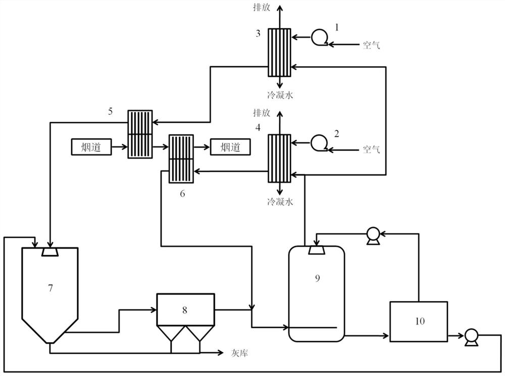
[0032] Such as figure 1 , is the desulfurization waste water zero discharge system for cascade utilization of flue gas waste heat of the present invention, comprising a first air intake device 1, a second air intake device 2, a first air heat exchanger 3, a second air heat exchanger 4, a first Flue gas heat exchanger 5 , second flue gas heat exchanger 6 , spray drying tower 7 , dust collector 8 , evaporative concentration tower 9 and desulfurization waste water pool 10 .

[0033] The first air intake device 1 is connected to the cold side inlet of the first air heat exchanger 3, the cold side outlet of the first air heat exchanger 3 is connected to the cold side inlet of the first flue gas heat exchanger 5, and the second air inlet The device 2 is connected to the cold side inlet of t...