Cutting type balloon dilatation device

A dilation device and a cutting-type technology, applied in dilators, balloon catheters, catheters, etc., can solve problems such as inability to dilate openings, organ tissue damage, etc., and achieve the effect of reducing damage

Pending Publication Date: 2021-01-26
SHANGHAI HEALING MEDICAL DEVICES CO LTD
View PDF0 Cites 0 Cited by
  • Summary
  • Abstract
  • Description
  • Claims
  • Application Information

AI Technical Summary

Problems solved by technology

[0006] Therefore, the technical problem to be solved by the present invention is that when there is a calcified area at the opening of the lesion, the existing balloon dilation

Method used


Image

  • Cutting type balloon dilatation device
  • Cutting type balloon dilatation device
  • Cutting type balloon dilatation device

Examples


Embodiment 1

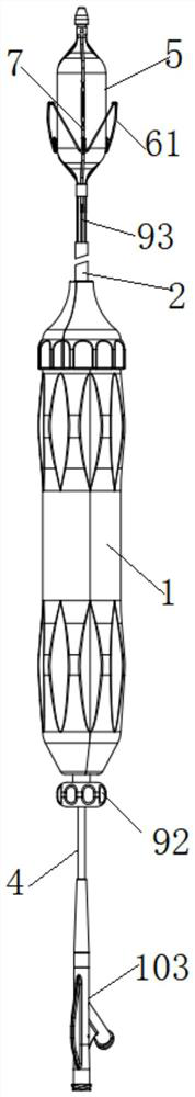
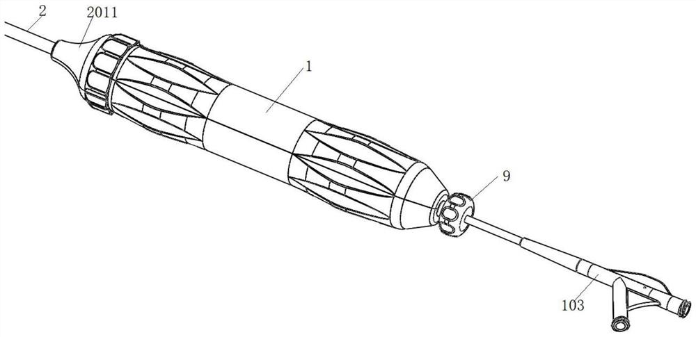
[0065] The present invention provides a cutting-type balloon expansion device, such as Figure 1 to Figure 10 As shown, it includes a handle shell 1 , a positioning bracket 61 , an inner tube 3 , an outer sheath 2 and a catheter 4 .

[0066] Wherein, the catheter 4 is sleeved outside the inner tube 3, and the outer sheath tube 2 is sleeved outside the catheter 4; the balloon 5 is sleeved outside the inner tube 3, and the proximal end of the balloon 5 is fixed on the distal end of the catheter 4; The distal end is sealed on the inner tube 3 , and the inner cavity of the balloon 5 communicates with the first passage between the catheter 4 and the inner tube 3 ; the distal end of the inner tube 3 is fixed with a tapered head. The outer sheath tube 2 , the inner tube 3 and the catheter 4 are all pierced on the handle shell 1 .

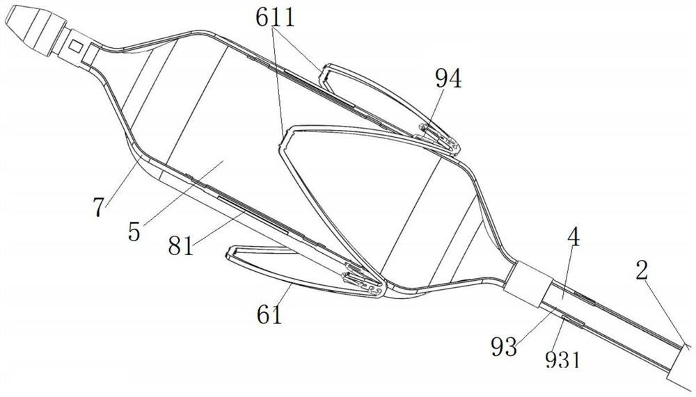
[0067] There are at least two positioning brackets 61, one end of any positioning bracket 61 is fixed on the catheter 4 or the balloon 5, and the other e...

Embodiment 2

[0112] This embodiment provides a cutting-type balloon dilation device. Compared with the dilation balloon 5 catheter 4 device provided in Embodiment 1, the only difference is:

[0113] The structure of positioning bracket 61 is different, as Figure 13 As shown, the positioning bracket 61 is in the form of a bar block or a bar column; in the non-working state, the positioning bracket 61 is distributed on the same straight line along the axial direction of the balloon 5; the proximal end of the positioning bracket 61 is fixed on the proximal end of the balloon 5 Above, the distal end of the positioning bracket 61 is suspended outside the balloon 5 , and in the working state, the positioning bracket 61 expands and deforms along the shape of the balloon 5 in the first direction.

[0114] or, as in Figure 12 As shown, the positioning bracket 61 includes a mounting portion 612 and a limiting portion 613. The distal end of the mounting portion 612 is fixed on the distal end of th...


PUM


Abstract

The invention discloses a cutting type balloon dilatation device. The cutting type balloon dilatation device comprises a balloon, a positioning support, a catheter, an inner tube and at least one blade. Due to the fact that the blade is arranged on the peripheral wall face of the balloon, when a hard guide wire arranged in the inner tube in the penetrating mode guides the cutting type balloon dilatation device to move towards a lesion position, even if a calcification area exists at an opening of the lesion position, the balloon slides and stretches into the opening, and the balloon does not touch the calcification area while not inflated; and then the balloon is inflated with gas, because the blade is arranged outside the balloon, before the balloon is filled with gas, the blade firstly encounters the calcification area, by moving or rotating the catheter, the calcification area is by the blade, so that the calcification area is reduced, and even if the balloon is filled with gas andthe balloon is in contact with the calcification area, the probability that the balloon moves forwards or backwards instantly along the calcification area is reduced, and then the probability that theadjacent organ tissue is damaged is reduced.

Description

technical field [0001] The invention belongs to the technical field of medical devices, and in particular relates to a cutting-type balloon expansion device. Background technique [0002] Artificial heart valve replacement surgery is a mature and safe treatment for heart valve diseases. The valve balloon is delivered through the femoral artery, and the artificial heart valve is delivered to the aortic valve area to open, thereby completing the implantation of the artificial valve and recovering. valve function. At present, before valve replacement surgery, it is necessary to use a cutting-type balloon expansion device to dilate and dredge the opening of the aortic valve lesion, which is conducive to the subsequent implantation of the valve stent, that is, to surround the three valve leaflets of the aortic sinus. The formed opening is expanded. [0003] The existing balloon expansion device includes an inner tube and a catheter that are sleeved sequentially from the inside ...

Claims


Application Information

Patent Timeline
IPC IPC(8): A61M29/04A61M25/10
CPCA61M25/1002A61M25/1018A61M29/02
Inventor 陈晓李阳王雪雪黄韬张铭宇刘冰冰郑嘉庚
Owner SHANGHAI HEALING MEDICAL DEVICES CO LTD
Why Eureka
Try Eureka