High-layer-thickness low-temperature sintering method and equipment for selective laser sintering

A laser sintering and low temperature sintering technology, applied in the field of additive manufacturing, can solve the problems of limited 3D molding speed, large laser energy loss, low sintering efficiency, etc., to achieve excellent electrical conductivity, high reusability, and increased sintering speed. Effect

Active Publication Date: 2021-01-29
HUNAN FARSOON HIGH TECH CO LTD
View PDF5 Cites 0 Cited by
  • Summary
  • Abstract
  • Description
  • Claims
  • Application Information

AI Technical Summary

Problems solved by technology

However, due to the large loss of laser energy after multiple refractions of polymers, high layer thickness cannot be sintered
As a result, the efficiency of sintering is low, and the polymer powder will not be completely melted, which also limits the speed of 3D molding

Method used


Image

  • High-layer-thickness low-temperature sintering method and equipment for selective laser sintering
  • High-layer-thickness low-temperature sintering method and equipment for selective laser sintering
  • High-layer-thickness low-temperature sintering method and equipment for selective laser sintering

Examples


Embodiment 1

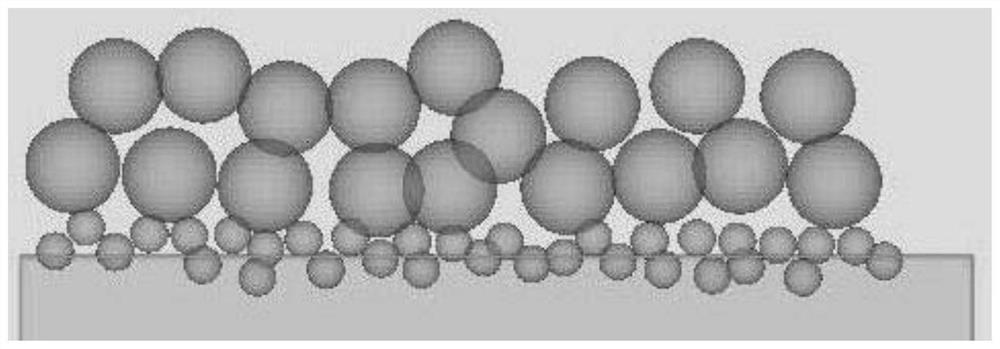
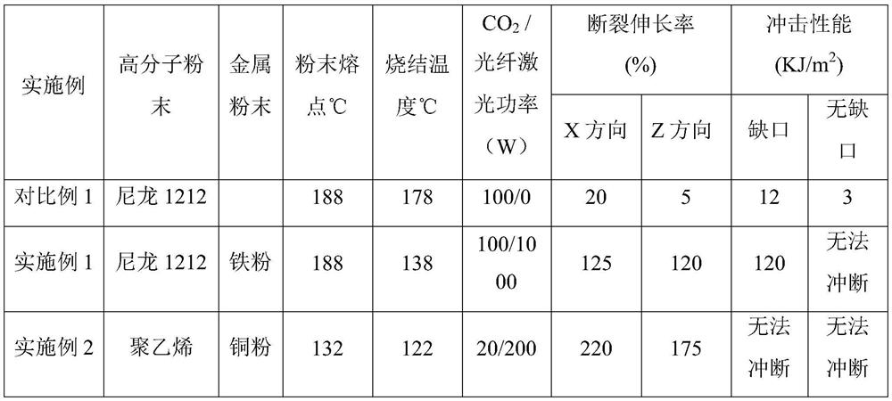
[0033](1) First, lay iron powder with a thickness of 0.02mm on the piston of the working cylinder, and then lay nylon 1212 with a thickness of 1.0mm on the iron powder, and preheat the above two layers of powder to a set temperature of 138°C. The set temperature is 50℃ lower than the melting point of nylon 1212;

[0034](2) Use CO with a wavelength of 10600nm and a rated power of 100W2The laser sinters the above two layers of powder with a sintering power of 100W and a sintered line spacing of 0.3mm, so that nylon 1212 powder is melted, and then sintered with a 1000W fiber laser with a wavelength of 1000nm rated power, and its sintering power is 1000W, sintered line spacing is 0.3mm;

[0035](3) Repeat steps 1 and 2 until the sintering of the workpiece is completed, and the sintering of the workpiece is completed.

Embodiment 2

[0037](1) First, lay copper powder with a thickness of 0.01mm on the piston of the working cylinder, and then lay polyethylene powder with a thickness of 0.3mm on the copper powder, and preheat the above two layers of powder to the set temperature of 122°C , The set temperature is 10°C lower than the melting point of the polyethylene powder;

[0038](2) Use CO with a wavelength of 10600nm and a rated power of 30W2The laser sinters the above-mentioned two layers of powder with a sintering power of 20W and a sintered line spacing of 0.08mm, so that the polyethylene powder is melted, and then sintered with a 200W fiber laser with a wavelength of 2000nm and a rated power. The sintering power is 200W, sintered line spacing is 0.08mm;

[0039](3) Repeat steps 1 and 2 until the sintering of the workpiece is completed, and the sintering of the workpiece is completed.

Embodiment 3

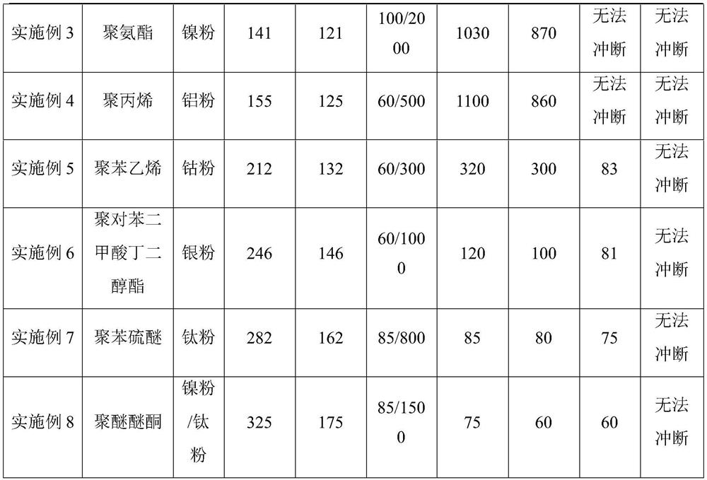
[0041](1) First, lay a layer of nickel powder with a thickness of 0.02mm on the piston of the working cylinder, and then pave a layer of polyurethane powder with a thickness of 0.5mm on the nickel powder, and preheat the above two layers of powder to a set temperature of 121°C. The set temperature is 20°C lower than the melting point of the polyurethane powder;

[0042](2) Use CO with a wavelength of 10600nm and a rated power of 100W2The laser sinters the above two layers of powder with a sintering power of 100W and a sintered line spacing of 0.5mm, so that the polyethylene powder is melted, and then sintered with a 2000W fiber laser with a wavelength of 405nm and a rated power. The sintering power is 2000W, the sintered line spacing is 0.5mm;

[0043](3) Repeat steps 1 and 2 until the sintering of the workpiece is completed, and the sintering of the workpiece is completed.


PUM

PropertyMeasurementUnit
particle sizeaaaaaaaaaa
wavelengthaaaaaaaaaa

Abstract

The invention provides a high-layer-thickness low-temperature sintering method for selective laser sintering. The method comprises the following steps: 1, laying metal powder with the layer thicknessof 0.01-0.05 mm on a piston of a working cylinder, then laying polymer powder with the layer thickness of 0.3-2.0 mm on the metal powder, and preheating the two layers of powder to a set temperature which is 10-150 DEG C lower than the melting point of the polymer powder; 2, sintering the two layers of powder by adopting a CO2 laser to melt the polymer powder, and then performing sintering by adopting an optical fiber laser; and executing step 1 and step 2 repeatedly until workpiece sintering is completed to obtain a workpiece. By means of the high-layer-thickness low-temperature sintering method, the sintering speed and forming efficiency of the selective laser sintering process are greatly increased, and the prepared workpiece is excellent in performance and can also serve as a good anti-static material due to its surface resistivity.

Description

Technical field[0001]The invention belongs to the technical field of additive manufacturing, and specifically relates to a high-layer thick low-temperature sintering method and equipment for selective laser sintering.Background technique[0002]Selective laser sintering technology is currently a commonly used rapid prototyping technology. This technology allows you to build a computer three-dimensional model of the target part without using tools for processing, and then use layering software to slice the three-dimensional model to spread the powder to the work The cylinder is then heated to a certain temperature, and finally a three-dimensional solid is obtained by laser sintering multiple layers of powder.[0003]The reason why polymer powder can be melted mainly has two energy sources. One energy source is the radiant heating of the lamp tube or filament on the upper part of the working cylinder. The upper heating energy is the main energy source for powder melting, accounting for ab...

Claims


Application Information

Patent Timeline
Patent Type & Authority Applications(China)
IPC IPC(8): B22F10/28B22F12/45B33Y10/00B33Y30/00B33Y70/10
CPCB33Y10/00B33Y30/00B33Y70/10Y02P10/25
Inventor 文杰斌罗秋帆李中元唐璟
Owner HUNAN FARSOON HIGH TECH CO LTD
Why Eureka
Try Eureka