Micro-milling burr inhibition method applied to folded waveguide slow wave structure
A technology of slow-wave structure and folded waveguide, which is applied in the directions of cleaning methods, cleaning methods and utensils, chemical instruments and methods using liquids, etc. Surface quality and other issues, to achieve the effect of satisfying high machined surface quality, suppressing the generation of burrs, and ensuring depth consistency
- Summary
- Abstract
- Description
- Claims
- Application Information
AI Technical Summary
Problems solved by technology
Method used
Image
Examples
Embodiment 1
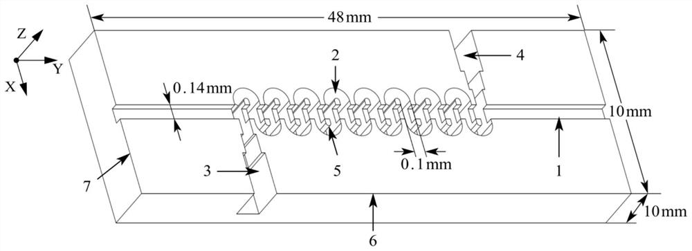
[0062] A micro-milling burr suppression method applied to folded waveguide slow-wave structures for processing such as figure 1 The slow wave structure shown. The overall slow wave structure is a cuboid of 48mm*10mm*10mm. S-shaped grooves 2 and straight grooves 1 that penetrate each other are distributed on the upper surface of the cuboid, and the two meet to form an island 5 . Among them, the S-shaped groove has a total of 75 cycles, the aspect ratio of the S-shaped groove reaches 255 μm / 100 μm, the island width is 48 μm, the span is 22.2 mm, and the straight groove width is 140 μm. The material of the slow wave structure is selected to be doped with Al with a volume fraction of 0.5% to 1.2% and a particle size of 50 to 100nm. 2 o 3 Granular dispersed oxygen-free copper. The dimensional accuracy of the processed slow wave structure is required to be better than ±2μm, and the surface roughness Ra should be better than 60nm.
[0063] In view of the complexity of the slow w...
Embodiment 2
[0067] A micro-milling burr suppression method applied to folded waveguide slow-wave structures for processing such as figure 1 The slow wave structure shown. The overall slow wave structure is a cuboid of 48mm*10mm*10mm. S-shaped grooves 2 and straight grooves 1 that penetrate each other are distributed on the upper surface of the cuboid, and the two meet to form an island. Among them, the S-shaped groove has a total of 75 cycles, the aspect ratio of the S-shaped groove reaches 255 μm / 100 μm, the island width is 48 μm, the span is 22.2 mm, and the straight groove width is 140 μm. The material of the slow wave structure is selected to be doped with Al with a volume fraction of 0.5% to 1.2% and a particle size of 50 to 100nm. 2 o 3 For the dispersed oxygen-free copper particles, the volume fraction of the dispersed oxygen-free copper doped in this embodiment is 1.1%. The dimensional accuracy of the processed slow wave structure is required to be better than ±2μm, and the su...
Embodiment 3
[0121] Compared with Embodiment 2, this embodiment has the same basic requirements for the processed slow wave structure.
[0122] Compared with Example 2, the process steps of this embodiment omit step B2, and the process methods of other steps are the same, and the cutting parameters are slightly adjusted within the selected range. The experimental results prove that after adopting the process steps of this example, the dimensional accuracy and machined surface quality of the workpiece are measured by using the VHX-1000 ultra-depth optical microscope and the ZYGO white light interferometer. Within the range, the surface roughness Ra is less than 60nm, and the PMMA auxiliary support material filled in the straight groove has a good overall suppression effect on micro-milling burrs. Since the PMMA auxiliary support material is not coated on the upper surface, there are a small amount of small-sized burrs at the top of the groove. within the acceptable range.
PUM
| Property | Measurement | Unit |
|---|---|---|
| particle size | aaaaa | aaaaa |
| surface roughness | aaaaa | aaaaa |
Abstract
Description
Claims
Application Information
 - R&D
- Intellectual Property
- Life Sciences
- Materials
- Tech Scout
- Unparalleled Data Quality
- Higher Quality Content
- 60% Fewer Hallucinations
Browse by: Latest US Patents, China's latest patents, Technical Efficacy Thesaurus, Application Domain, Technology Topic, Popular Technical Reports.
© 2025 PatSnap. All rights reserved.Legal|Privacy policy|Modern Slavery Act Transparency Statement|Sitemap|About US| Contact US: help@patsnap.com


