
Ultraviolet gas analysis method and ultraviolet gas analyzer

A gas analyzer and gas analysis technology, applied in the field of measurement, can solve the problems of affecting the measurement accuracy of gas concentration, the error of consistent measurement results, and high cost, and achieve the effects of low maintenance cost, long service life and improved shock resistance

Active Publication Date: 2021-02-19
HUBEI RUIYI AUTOMATIC CONTROL SYST CO LTD
View PDF18 Cites 3 Cited by
  • Summary
  • Abstract
  • Description
  • Claims
  • Application Information

AI Technical Summary

Problems solved by technology

Since hydrogen sulfide gas has a significant absorption peak at 228 nanometers and almost no absorption at 361 nanometers, these two bands can be used as measurement and reference channels respectively to form a differential measurement system. Although this scheme achieves reference measurement, However, it contains two detectors and a semi-reflective mirror, which has a complex structure and high cost, and the consistency difference between the two detectors will also bring errors to the measurement results and affect the measurement accuracy of gas concentration.
[0009] To sum up, in the prior art, the reference measurement is realized through the double optical path structure with the light slicer and / or semi-transparent and semi-reflective lens, resulting in poor reliability, complex structure and high cost of the existing gas analyzers

Method used


Image

  • Ultraviolet gas analysis method and ultraviolet gas analyzer
  • Ultraviolet gas analysis method and ultraviolet gas analyzer
  • Ultraviolet gas analysis method and ultraviolet gas analyzer

Examples


Embodiment Construction

[0040] In order to make the purpose, technical solution and advantages of the present invention clearer, the embodiments of the present invention will be further described below in conjunction with the accompanying drawings.

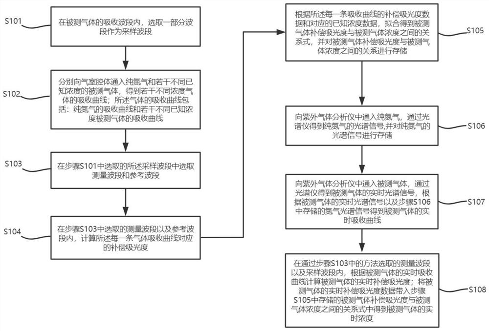
[0041] Please refer to figure 1 , a kind of ultraviolet gas analysis method, specifically comprises the following steps:

[0042] S101: within the absorption band of the gas to be measured, select a part of the band as the sampling band;

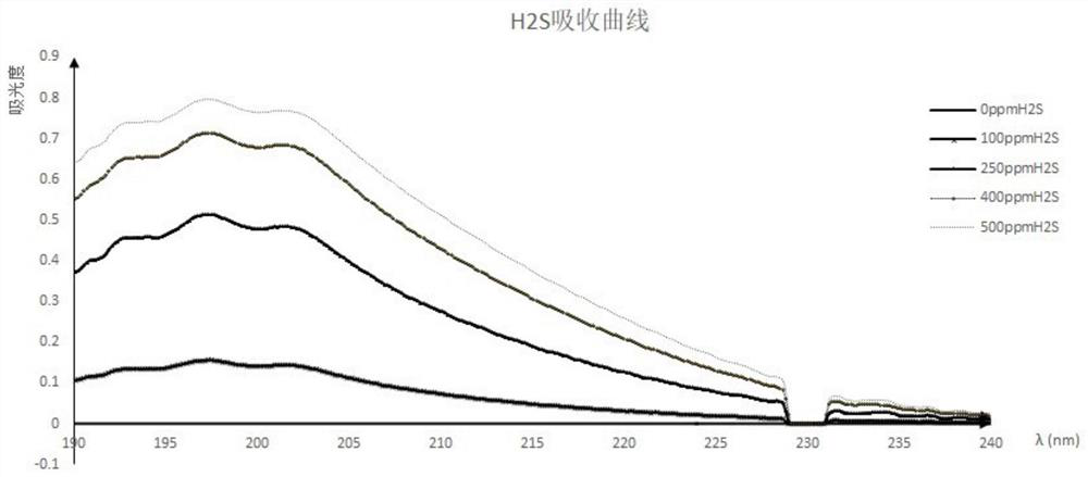
[0043] In the background technology and examples of the present application, hydrogen sulfide gas is used as an example, but this is not limited; it is known that hydrogen sulfide gas absorbs ultraviolet light at a wavelength of 190-240nm. When measuring other measured gases, different gases The absorption band of ultraviolet light will be different.

[0044] The sampling band is selected in the following way: by passing pure nitrogen into the gas chamber cavity, the pure nitrogen spectrum is obtained through spectro...


PUM


Abstract

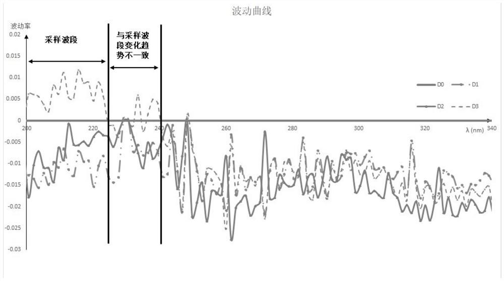
The invention provides an ultraviolet gas analysis method and an ultraviolet gas analyzer, and the method comprises the steps: selecting a part of wavebands from wavebands with consistent fluctuationchange trends as sampling wavebands in an absorption waveband of detected gas; introducing a plurality of measured gases with different known concentrations into the cavity of a gas chamber, selectinga measurement waveband and a reference waveband from the sampling wavebands, and calculating the compensation absorbance of the measured gas; obtaining a relationship between the compensation absorbance of the measured gas and the concentration of the measured gas through fitting, and storing the relationship; when measured gas is introduced into the ultraviolet gas analyzer, obtaining an absorption curve of the measured gas in real time, and substituting real-time compensation absorbance obtained by dividing the average absorbance of the measurement wave band by the average absorbance of thereference wave band into a stored concentration formula to obtain real-time concentration data of the measured gas. The method has the advantages that reference measurement is achieved only through the single-channel air chamber in combination with a software algorithm, long-term drifting is eliminated, stability is good, cost is low, and real-time performance is good.

Description

technical field [0001] The invention relates to the field of measurement technology, in particular to an ultraviolet gas analysis method and an ultraviolet gas analyzer. Background technique [0002] Biogas is a flammable mixed gas, generally containing methane, carbon dioxide, ammonia, hydrogen and hydrogen sulfide and other gases. In the past, biogas analyzers were usually mainly used to detect the content of indicator gases such as methane, carbon dioxide and oxygen, and did not pay attention to the content of hydrogen sulfide. However, hydrogen sulfide in biogas is a harmful gas, which is harmful to pipelines, instruments and equipment. It has a strong corrosive effect, and if it leaks in the air, it will pollute the atmosphere and endanger human health. Therefore, the monitoring of hydrogen sulfide content in biogas cannot be ignored. [0003] my country's environmental protection standards strictly stipulate that when using biogas energy, the H2S content in the bioga...

Claims


Application Information

Patent Timeline
Patent Type & Authority Applications(China)
IPC IPC(8): G01N21/33
CPCG01N21/33
Inventor 熊友辉石平静罗海峰程静伟
Owner HUBEI RUIYI AUTOMATIC CONTROL SYST CO LTD
Learn More