Continuous low-temperature plasma powder treatment and ball milling production device and method thereof

A technology of low-temperature plasma and production equipment, which is applied in the field of powder material processing and powder metallurgy, can solve the problems of poor treatment effect, unevenness, incomplete particle treatment, etc., and achieve the effect of reducing reaction activation energy and refining grains

Pending Publication Date: 2021-03-09
SOUTH CHINA UNIV OF TECH
View PDF2 Cites 4 Cited by
  • Summary
  • Abstract
  • Description
  • Claims
  • Application Information

AI Technical Summary

Problems solved by technology

[0009] If the large-scale application of low-temperature plasma treatment of powder materials is extended to the fields of metal powder and oxide ceramic powder, the following problems must be solved: (1) There is powder accumulation and agglomeration between particles during powder plasma treatment, The surface of the particles that are not exposed to the plasma atmosphere cannot be treated, and it is difficult to realize the treatment of all the particles, resulting in incomplete and uneven treatment of the particles, and the treatment effect is poor; (2) to achieve controllable plasma discharge intensity and energy
Since the bond energy of polymer materials is much lower than that of metal and oxide materials, the conventional plasma energy used for polymer material treatment is low, and it is not suitable for metal materials and oxide materials; (3) Generally, dielectric barrier plasma discharge or radio frequency plasma discharge has limited space. Therefore, the development of large-area plasma discharge structure is the key problem to solve the large-scale preparation of plasma or process powder.

Method used


Image

  • Continuous low-temperature plasma powder treatment and ball milling production device and method thereof
  • Continuous low-temperature plasma powder treatment and ball milling production device and method thereof
  • Continuous low-temperature plasma powder treatment and ball milling production device and method thereof

Examples


Embodiment 1

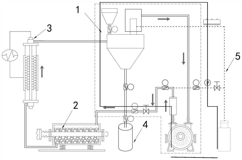
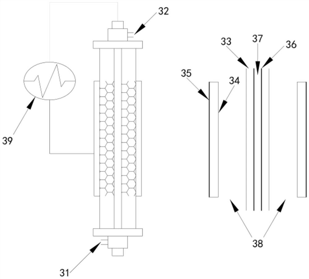
[0046] Step 1. Start the controllable atmosphere system first, evacuate the entire pipeline and ball mill chamber to below 1Pa, and then replace it with argon gas; secondly, start the vibrating ball mill and the powder circulation delivery pipeline system, and finally start the low-temperature plasma discharge pipeline and its cooling system.

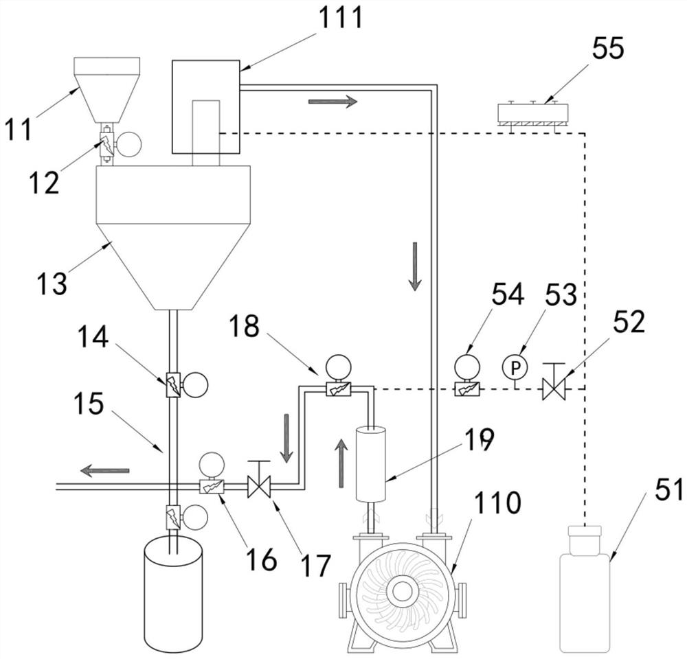
[0047] Step 2. Feed 15 kg of ultra-fine Fe powder material into the feeding bin at one time, and automatically enter the temporary storage bin under the protection of argon through the feeding port of the feeding bin. The gas is separated from solid and gas in the backflushing system, and the remaining solid The material powder enters the material circulation system through the rotary feeding valve and the feeding pipeline; among them, the inner diameter of the powder circulation pipeline is selected as 35mm, the mass ratio of material powder and gas is 5:1, and the pressure of circulating gas and discharge gas is -0.3bar;

[0048] Step 3...

Embodiment 2

[0051] Step 1. Start the controllable atmosphere system first, evacuate the entire pipeline and ball mill chamber to below 1Pa, and then replace it with argon; secondly, start the powder circulation delivery pipeline system, and finally start the low-temperature plasma discharge pipeline and its cooling system.

[0052] Step 2. Feed 15 kg of ultra-fine Fe powder material into the feeding bin at one time, and automatically enter the temporary storage bin under the protection of argon through the feeding port of the feeding bin. The gas is separated from solid and gas in the backflushing system, and the remaining solid The material powder enters the material circulation system through the rotary feeding valve and the feeding pipeline; among them, the inner diameter of the powder circulation pipeline is selected as 60mm, the mass ratio of material powder and gas is 12:1, and the pressure of circulating gas and discharge gas is -0.1bar;

[0053] Step 3. The above-mentioned superfin...

Embodiment 3

[0057] Step 1. Start the controllable atmosphere system first, evacuate the entire pipeline and ball mill chamber to below 1Pa, and then replace it with argon gas; secondly, start the vibrating ball mill and the powder circulation delivery pipeline system, and finally start the low-temperature plasma discharge pipeline and its cooling system.

[0058] Step 2. Mix 8 kg of WO3 and graphite according to the carbon content of 20% by mass, pre-mill the above-mentioned mixed powder in a vibrating ball mill for 1 hour, and then feed it into the feeding bin at one time, and automatically pass through the feeding bin. The feed port enters the temporary storage bin under the protection of argon gas, and the gas realizes solid-gas separation in the blowback system, and the remaining solid material powder enters the material circulation system through the rotary feeding valve and the feeding pipeline; among them, the inner diameter of the powder circulation pipeline is selected to be 50 m...


PUM


Abstract

The invention discloses a continuous low-temperature plasma powder treatment and ball milling production device and a method thereof. The device comprises a powder circulating conveying pipeline system, a ball mill, a low-temperature plasma discharge pipeline, a vacuum discharge system and a controllable atmosphere system. According to the device, the powder to be treated is circularly conveyed ina pipeline under controllable air pressure and circulation speed by utilizing the powder circulating conveying system, and in the process, on one hand, the ball mill is introduced in the powder pipeline conveying process to perform ball milling refining or alloying on material powder; and on the other hand, a dielectric barrier discharge structure is introduced into part of the powder conveying pipeline to perform plasma discharge treatment on the ball-milled powder flowing in the pipeline. On the basis of a common powder circulating conveying technology, near-normal-pressure discharge plasmas in the pipeline cooperate with mechanical ball milling to jointly treat powder. The device can also be used for carrying out surface cyclic modification treatment on conventional metal, macromolecule or oxide powder.

Description

technical field [0001] The invention belongs to the technical field of powder material processing and powder metallurgy, and relates to plasma gas powder surface treatment and ball milling technology, in particular to a continuous low-temperature plasma powder treatment and ball milling production device. Background technique [0002] With the rapid development of new materials and intelligent manufacturing industries, the development of low-cost, pollution-free, high-performance functional powder preparation technology is the key basis for the fields of electronic information, machinery manufacturing, biomedicine, national defense and military. On the one hand, low-temperature plasma has enough high-energy active substances to excite, ionize or break bonds in reactant molecules, and on the other hand, it will not pyrolyze or ablate the processed materials, so it has unique application value on the surface of modified powder materials . [0003] Plasma is the fourth state o...

Claims


Application Information

Patent Timeline
Patent Type & Authority Applications(China)
IPC IPC(8): B02C21/00B02C17/10B02C17/14B22F9/14B22F9/04C01G41/02C01B32/21C01B32/949
CPCB02C21/00B02C17/10B02C17/14B22F9/14B22F9/04C01G41/02C01B32/21C01B32/949B22F2009/043C01P2004/80C01P2004/62C01P2004/03C01P2002/88
Inventor 朱敏鲁忠臣曾美琴欧阳柳章胡仁宗王辉
Owner SOUTH CHINA UNIV OF TECH
Why Eureka
Try Eureka