

Electrochemiluminescence immunosensor
A technique of electrochemistry and luminescence immunity, applied in the field of detection, can solve the problems of weak luminescence signal, insufficient detection sensitivity, and insignificant quenching effect, and achieve the effects of easy portability, improved sensitivity, and suitable for clinical rapid detection.
- Summary
- Abstract
- Description
- Claims
- Application Information
AI Technical Summary
Problems solved by technology
Method used
Image

Examples
Embodiment 1
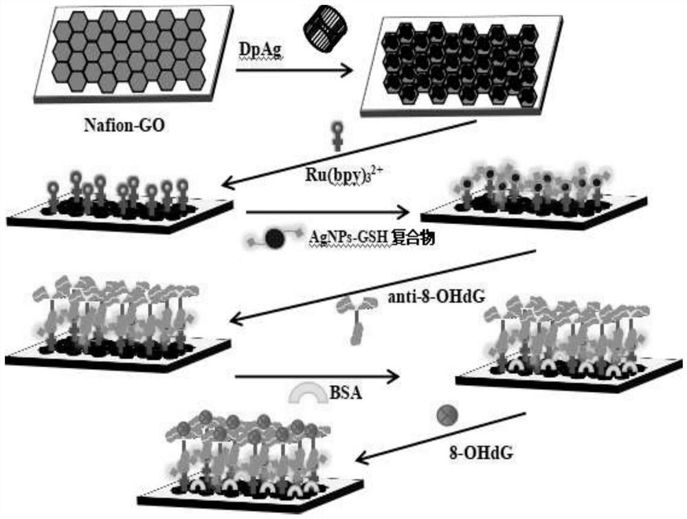
[0044] Embodiment 1 An electrochemiluminescent immunosensor and its application method
[0045] The sensor of this embodiment uses octahydroxydeoxyguanosine (8-OHdG) as the detection object. 8-OHdG is an oxidative adduct produced by active oxygen free radicals such as hydroxyl free radicals and singlet oxygen attacking the 8th carbon atom of guanine base in DNA molecules, and is a kind of oxidative damage to DNA. The product has been used as an indicator of various inflammatory diseases.
[0046] 1. Preparation of reagents
[0047] Preparation of phosphate buffer solution (PBS): prepare 0.1mol / L PBS buffer solution, weigh 7.098g of disodium hydrogen phosphate, 6.805g of potassium dihydrogen phosphate and 3.728g of potassium chloride, put them in a beaker, add a certain amount of deionized After soaking in water, place it in an ultrasonic oscillator to sonicate and stir until the solid is fully dissolved, then transfer all of it to a 500mL measuring bottle, and set the volume...
experiment example 1
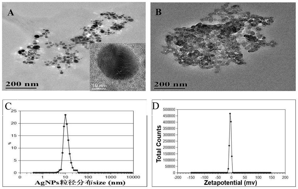
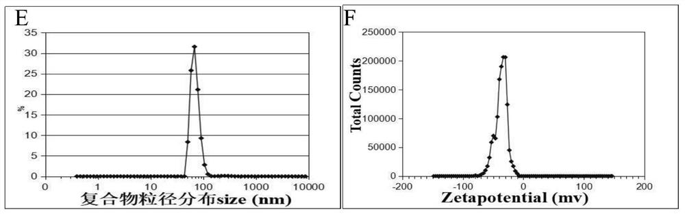
[0069] Experimental Example 1 Characterization of Synthetic Nanomaterials
[0070] The AgNPs ( figure 2 -A) and the complex after AgNPs aggregated by GSH ( figure 2 -B) The appearance morphology is characterized.
[0071] Depend on figure 2 -A, it can be seen that AgNPs are scattered in spots under the transmission electron microscope. figure 2 -C, figure 2 -D It can be seen that its dominant distribution particle size is 10.10nm (23.41%), and its dominant distribution potential is -5.06mV. figure 2 -B is the AgNPs:GSH complex, which is distributed in a bead-like aggregate, from figure 2 -E and figure 2 -F shows that the dominant particle size of the complex is 68.06nm (31.57%), and the dominant potential distribution is -33.89mV.
[0072] It shows that GSH has successfully aggregated AgNPs through covalent binding, and the negative charge increases, which can enhance the complex and Ru(bpy) 3 2+ of electrostatic adsorption.
experiment example 2
[0073] Experimental example 2 Comparison of ECL signal strength after superposition of each layer of sensor material
[0074] On the basis of Example 1, after the graphene was modified during the sensor construction process, nano-silver was electrodeposited and the luminescent Ru(bpy) was absorbed 3 2+ The electrodes after incubation with AgNPs:GSH complexes, incubation with anti-8-OHdG, and BSA-blocked electrodes were used to detect 8-OHdG, respectively.
[0075] The result is as image 3 shown. Curve a in the figure is the ECL signal after the bare electrode is modified with Nation dispersed graphene. Curve b is a layer of nano-silver particles electrodeposited on the surface of the electrode, and absorbs the luminous substance Ru(bpy) 3 2+ post-ECL signal. Continue to incubate the AgNPs:GSH complex (curve c), and the ECL intensity increases significantly. When the incubated anti-8-OHdG hindered the electron transport on the electrode surface (curve d), and after BSA bl...
PUM
 Abstract
Description
Claims
Application Information