
Anode mud treatment method

A treatment method and anode slime technology, which is applied in the field of non-ferrous metallurgy technology, can solve the problems of restricting anode slime pyroprocessing technology, low comprehensive utilization rate of valuable metals, and low equipment treatment efficiency, so as to reduce fugitive emissions and facilitate Effects of recovering base metals and saving flux

Pending Publication Date: 2021-03-26
CHINA ENFI ENGINEERING CORPORATION
View PDF7 Cites 0 Cited by
  • Summary
  • Abstract
  • Description
  • Claims
  • Application Information

AI Technical Summary

Problems solved by technology

Lead anode slime treatment generally adopts combined fire method and wet method, but the production cycle of this technology is long and the production environment is poor
Copper anode mud fire treatment mostly adopts imported Kaldor furnace, which requires a large investment and returns more materials, and it is inconvenient to recycle the slag produced
The commonly used copper anode slime wet treatment technology consumes a lot of reagents, produces a lot of wastewater, and has a long process flow and poor applicability
[0003] Although the existing pyrolysis process for anode slime is simple in process, strong in adaptability, and simple in equipment, there are still many problems, such as low comprehensive utilization rate of valuable metals, high energy consumption, low degree of automation, and poor operating environment , Raw materials need to be stockpiled for pre-oxidation, and the processing efficiency of equipment is low, which cannot meet the turnover requirements of modern smelters, etc., and these factors restrict the development of anode mud fire treatment technology

Method used


Image

  • Anode mud treatment method

Examples


Embodiment 1

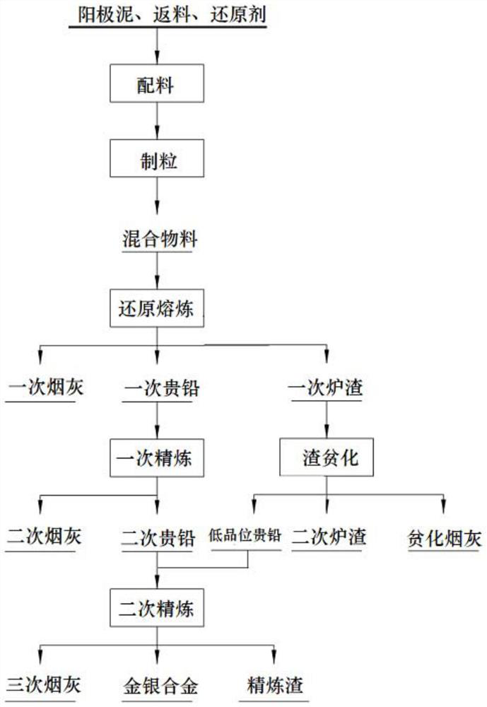
[0062] The lead anode slime (containing 20% ​​of Pb, 18% of Sb, 5% of Bi, 10% of Ag, 10% of As, the percentage (%) here refers to the mass percentage) and crushed coal were mixed according to the mass ratio of 100:5 to obtain the first A mixture of materials, at the same time mixed into the return material, the return material is discharged from the three-time soot from the silver furnace. Then, the first mixed material is conveyed to a cylinder granulator through a belt for granulation, and the cylinder granulator makes the first mixed material into granules, and the moisture content of the material is controlled not to exceed 35%.

[0063] Before the granulated first mixed material is sent to the oxygen-enriched side-blowing furnace, it is continuously fed into the oxygen-enriched side-blowing furnace through the feeding port. The oxygen-enriched side-blowing furnace uses natural gas as fuel and oxygen-enriched air as combustion-supporting gas, wherein the oxygen concentrati...

Embodiment 2

[0070] It is basically the same as Example 1, except that the anode slime used is copper anode slime after decopper removal, and the components of the anode slime are Pb 15%, Sb 3%, Bi 2%, Ag 10%, and Cu 1%.

Embodiment 3

[0072] The difference with Embodiment 1 is that the oxygen-enriched side-blowing furnace uses pulverized coal as fuel.


PUM


Abstract

The invention provides an anode mud treatment method. The anode mud treatment method comprises the steps that anode mud and a reducing agent are mixed according to a preset weight ratio to obtain a first mixed material, and reduction smelting is conducted on the first mixed material at 800-1000 DEG C to obtain primary precious lead, primary furnace slag and primary soot; primary refining is conducted on the primary precious lead through an antimony white furnace so that base metal in the primary precious lead can volatilize to obtain secondary precious lead and secondary soot; and then secondary refining is conducted on the secondary precious lead through a silver separating furnace to obtain gold-silver alloy and tertiary soot. The anode mud treatment method provided by the invention hasthe characteristics of no need of a slag former and / or a flux, low slag rate, longer service life of the refractory material, large treatment capacity, high treatment efficiency, low energy consumption, environmental friendliness and the like.

Description

technical field [0001] The invention relates to the technical field of smelting of non-ferrous technology, in particular to a method for treating anode slime. Background technique [0002] A large amount of rare and precious metals will be enriched in the anode slime produced in the electrolytic refining process of non-ferrous metals such as copper and lead. These anode slimes are important sources for extracting gold, silver, antimony, bismuth, tellurium and other rare and precious metals. The treatment of lead anode slime generally adopts combined fire method and wet method, but the production cycle of this technology is long and the production environment is poor. Copper anode mud fire treatment mostly adopts the imported Kaldor furnace, which requires a large investment, and there are many returned materials, and the recovery of the produced slag is inconvenient. The commonly used wet treatment technology of copper anode slime consumes a lot of reagents, produces a lot ...

Claims


Application Information

Patent Timeline
Patent Type & Authority Applications(China)
IPC IPC(8): C22B7/00C22B7/02C22B11/02C22B13/02C22B30/02
CPCC22B7/001C22B13/025C22B7/02C22B30/02C22B11/023Y02P10/20
Inventor 许良彭思尧吴卫国梁帅表
Owner CHINA ENFI ENGINEERING CORPORATION
Learn More